
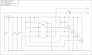
Electric candle simulation schematic

More: How do we get the light off? Blow against the thermistor so that it cools, bladder, if necessary several times and the light goes out slowly. A thermistor has cooled a higher resistance, thus reducing the current passes through. This will also mean less power to the base of the transistor and hence the transistor. The light goes out. With the variable resistor, you can set the temperature at which the light will light. Turn the shaft of the potentiometer so that the light goes off. Wait until the thermistor cools down. Then turn the potentiometer until the lamp is lit, and then turn it right back so the light just goes out. Check the position of the lamp and the thermistor. The filament in the bulb should be as close to the thermistor are. R1 = 10kΩ NTC R2 = 2.2 kOhm P1 = 10 kOhm T1, T2 = BC548 La1 = 12 V/50 mA
The described circuit utilizes a thermistor, a type of temperature-sensitive resistor, to control the operation of a light bulb based on temperature changes. The thermistor (designated as R1, a 10 kΩ NTC) decreases in resistance when heated, which in turn affects the voltage across it. This decrease in resistance allows more current to flow into the base of the first transistor (T1, BC548), which is configured as a switch.
As the current increases at the base of T1, it turns on, allowing current to flow from the collector to the emitter, which in turn powers the second transistor (T2, also a BC548). The activation of T2 allows current to flow through the light bulb (La1, rated at 12 V and 50 mA), illuminating it. The positioning of the thermistor close to the light bulb ensures that the heat generated by the bulb can maintain the thermistor's temperature, keeping the circuit active as long as the heat is sufficient.
To turn off the light, one can blow on the thermistor, which cools it down and increases its resistance. This causes a reduction in current flowing to the base of T1, eventually turning it off, which also turns off T2 and the light bulb.
A variable resistor (P1, 10 kΩ) is included in the circuit to adjust the sensitivity of the thermistor. By turning the potentiometer, the threshold temperature at which the light turns on can be set. The process involves adjusting the potentiometer until the light turns on and then slightly turning it back to find the point where the light just goes off.
This circuit effectively demonstrates a simple thermal switch mechanism, where the light's operation is directly tied to the thermal response of the thermistor, mimicking the behavior of a candle being lit or extinguished through thermal energy. The careful arrangement of components ensures reliable operation and allows for user adjustment of the temperature threshold.For a candle to burn, we need a heat source (the flame of a match) and to extinguish it, you do it just to blow out. The following circuit behaves similarly. If you use your fingers heats the thermistor, its resistance decreases. The tension on the thermistor is lower and there is more current to the base of the left transistor. From here, more power to the base of the right transistor, which will guide and the light comes on. If the light and the thermistor close to each other, the heat of the thermistor heat lamp and the lamp will remain lit.
How do we get the light off? Blow against the thermistor so that it cools, bladder, if necessary several times and the light goes out slowly. A thermistor has cooled a higher resistance, thus reducing the current passes through. This will also mean less power to the base of the transistor and hence the transistor. The light goes out. With the variable resistor, you can set the temperature at which the light will light. Turn the shaft of the potentiometer so that the light goes off. Wait until the thermistor cools down. Then turn the potentiometer until the lamp is lit, and then turn it right back so the light just goes out.
Check the position of the lamp and the thermistor. The filament in the bulb should be as close to the thermistor are. R1 = 10k? NTC R2 = 2.2 kOhm P1 = 10 kOhm T1, T2 = BC548 La1 = 12 V/50 mA 🔗 External reference
Related Circuits

This photoelectric smoke detector circuit utilizes one LED and two light-dependent resistors (LDRs) to detect smoke and activate an alarm. The LM1801 integrated circuit is the optimal choice for this application. The photoelectric smoke detector circuit operates based on the...

The schematic for controlling the motors is divided into three main sections, each serving a distinct function. The primary components featured in the schematic include the PIC 18F252 microcontroller, the SN754410 motor driver, and 2N2222 transistors. At the top...
The microcontroller program is designed to support two communication protocols: the one-wire bus utilized by the DS1820 temperature sensor and the serial protocol used for communication with a computer. Upon power-up, the program retrieves data from the temperature sensors...
The simplest method of detecting metal is through a beat frequency oscillator. The circuit consists of two balanced oscillators: one serves as the detector element while the other provides a reference signal. The reference oscillator frequency is set to...
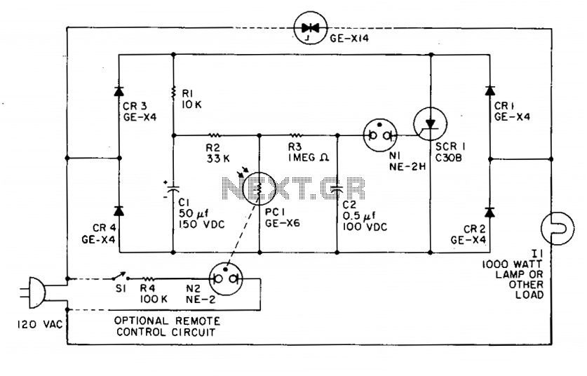
CR1, CR2, CR3, and CR4 form a bridge circuit with the SCR across the DC legs. When illuminated, the photoconductor PCI allows CI to charge through R1 to approximately 150 VDC. The resistance of PCI is low under illumination,...
Can be directly connected to CD players, tuners and tape recorders. Simply add a 10K Log potentiometer (dual gang for stereo) and a switch to cope with the various sources you need. Q6 & Q7 must have a small...