Electric-crowbars

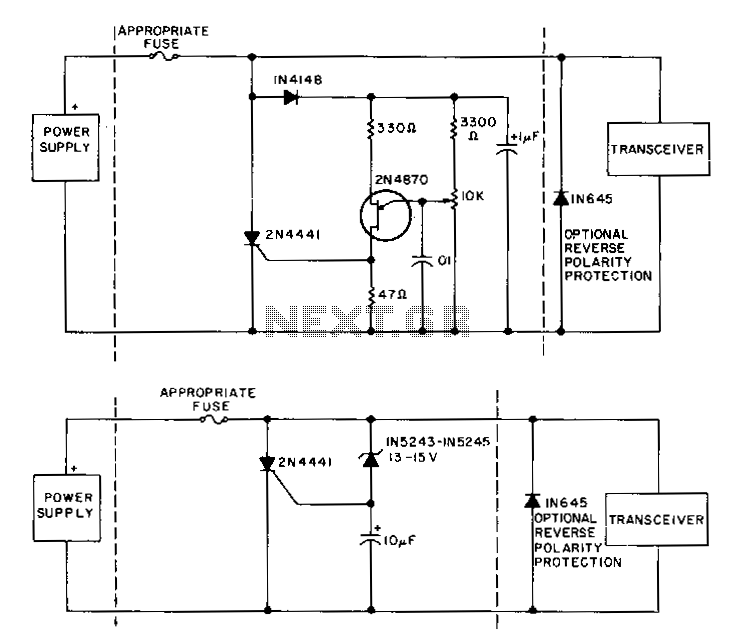
To prevent issues when using 12-V power supplies with mobile transceivers, particularly during a short-circuit failure of the series pass transistor, crowbar circuits offer protection by clamping the power line and blowing the fuse within microseconds of an overvoltage condition. It is advisable to integrate the crowbar directly into the transceiver. The primary distinction between the two circuits is that the less complex circuit B relies on component tolerances for the exact trigger level, whereas circuit A incorporates a unijunction trigger to allow for precise adjustment of the operating point.
Crowbar circuits are essential in protecting sensitive electronic devices, such as mobile transceivers, from overvoltage conditions that can occur due to various faults, including short circuits. The crowbar circuit operates by monitoring the voltage level and, upon detecting an overvoltage condition, it activates a thyristor or similar device which effectively shorts the power supply. This action rapidly diverts the excess voltage away from the load, ensuring that the transceiver is safeguarded.
Incorporating a crowbar circuit directly into the transceiver design enhances reliability and reduces the risk of damage. The circuit typically includes a fuse that is designed to blow quickly, thereby cutting off power to the transceiver within microseconds of detecting an overvoltage event. This rapid response is crucial in preventing damage to the internal components of the transceiver, which may be sensitive to voltage spikes.
The distinction between circuit A and circuit B is significant in terms of design complexity and performance. Circuit A, which utilizes a unijunction transistor (UJT) trigger, allows for a more precise setting of the trigger level, enabling the designer to define the exact voltage at which the crowbar will activate. This precision is beneficial in applications where voltage tolerances are critical. Conversely, circuit B, being less complex, relies on the inherent tolerances of its components, which may lead to variability in the trigger level. While circuit B may be easier to implement, it may not provide the same level of protection consistency as circuit A.
Overall, the implementation of a crowbar circuit within a mobile transceiver is a prudent design choice that enhances the robustness of the device against overvoltage conditions, ensuring longevity and reliability in various operating environments.To avoid grief when using 12-V power supplies with mobile transceivers, especially when there is a short -circuit failure of the series pass transistor, crowbar circuits provide protection by clamping the power line and blowing the fuse within microseconds of an overvoltage condition. It is a good idea to incorporate the crowbar directly into the transceiver. The main difference between the two circuits is that less complex circuit B depends on component tolerances for the exact trigger level, while the circuit A includes a unijunction trigger to permit precise setting of the operating point.