
Electrical Systems and Circuits

The central door locking system is a sophisticated assembly designed to enhance vehicle security and user convenience. It integrates several components, including an electronic control module (ECM), actuators, sensors, and transmitters. The ECM serves as the brain of the system, processing inputs from the door key switch and remote control, and managing the output to the locking mechanisms via the actuators.
The electro-mechanical devices, such as solenoids or electric motors, are responsible for the physical locking and unlocking of the doors. When the driver or passenger uses the key or remote control, the corresponding switch sends a signal to the ECM. The ECM then energizes the actuators, which engage or disengage the locking mechanism.
Remote controls utilize either infrared or radio frequency technologies to communicate with the ECM. Infrared systems require a direct line of sight between the remote and the ECM, while radio frequency systems allow for greater flexibility, enabling operation from various angles and distances. The unique code transmitted by the remote ensures that only the designated key can operate the locking system, preventing unauthorized access.
Interior door handles are designed to provide an additional layer of safety by allowing occupants to unlock the doors from inside the vehicle. This feature is critical in emergency situations, where quick access to exit the vehicle is necessary.
Overall, the central door locking system exemplifies modern automotive engineering, combining mechanical and electronic elements to provide a reliable and user-friendly solution for vehicle access and security.A central door locking system permits all doors, often including the boot lid or tailgate, to be locked centrally from the driver`s door and, normally includes the front passenger`s door also. The locking and unlocking action is produced by an electro-mechanical device, such as a solenoid or an electric motor.
The door key operates a switch which controls the electrical supply that actuates the door lock mechanism and the remote control activates a switching circuit in the electronic control module (ECM) that also actuates the locking mechanism. For safety and convenience, the interior door handles also operate the unlocking mechanism. The remote control operates in much the same way as the remote control for a domestic television. A unique code is transmitted from the remote control which is normally contained in the ignition key.
Two types of transmitter are used, infra-red and radio frequency. The electronic control module (ECM) that controls the supply of current to the door lock actuators contains a sensor that detects infra-red signals or, in the case of radio frequency systems, an aerial to detect the radio frequency signal. The remote signal is normally effective over a range of several metres. Figure. 12. 1 shows the general principle of central locking systems. 🔗 External reference
Related Circuits
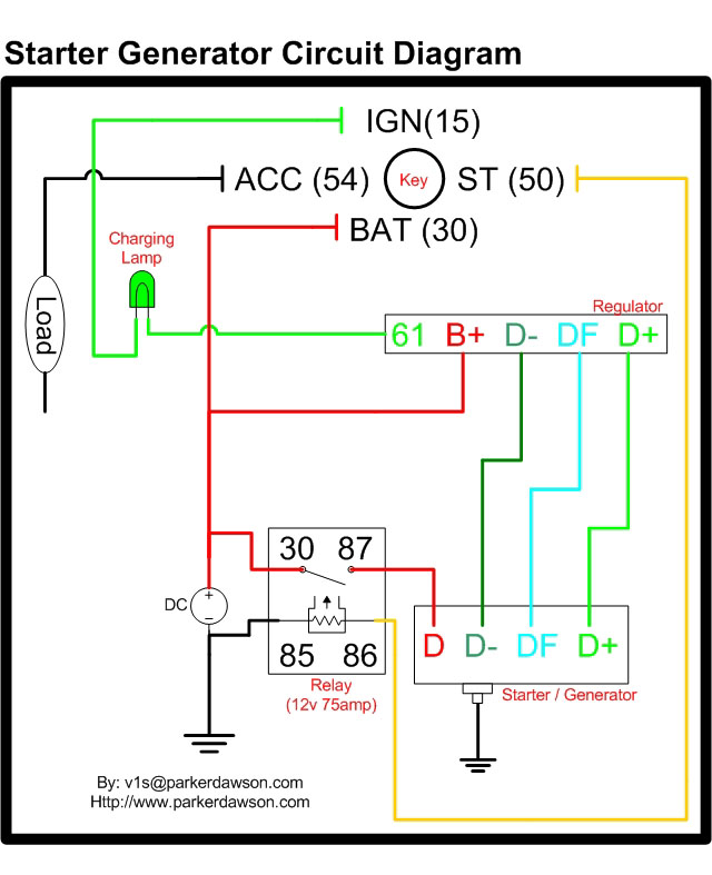
Circuit diagrams for both a Bosch and a Delco-Remy Starter-Generator are available, noting that the circuits differ. Due to a computer crash, the original diagrams and the associated email address were lost. However, in May 2004, both the email...
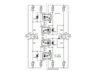
When the SDA (Serial Data) lines on both the left and right lines are high (logic level 1), the circuit remains in a quiescent state, and the optoisolators IC1 and IC2 are not activated. In this circuit, the Serial...
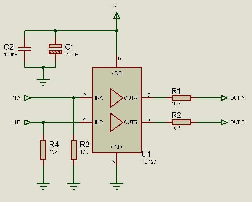
MOSFETs cannot simply be connected to the drive signal and expected to function correctly. Due to their construction, driving MOSFETs can be complex, particularly for beginners. Many users frequently seek assistance with MOSFET drive issues on various blogs, websites,...
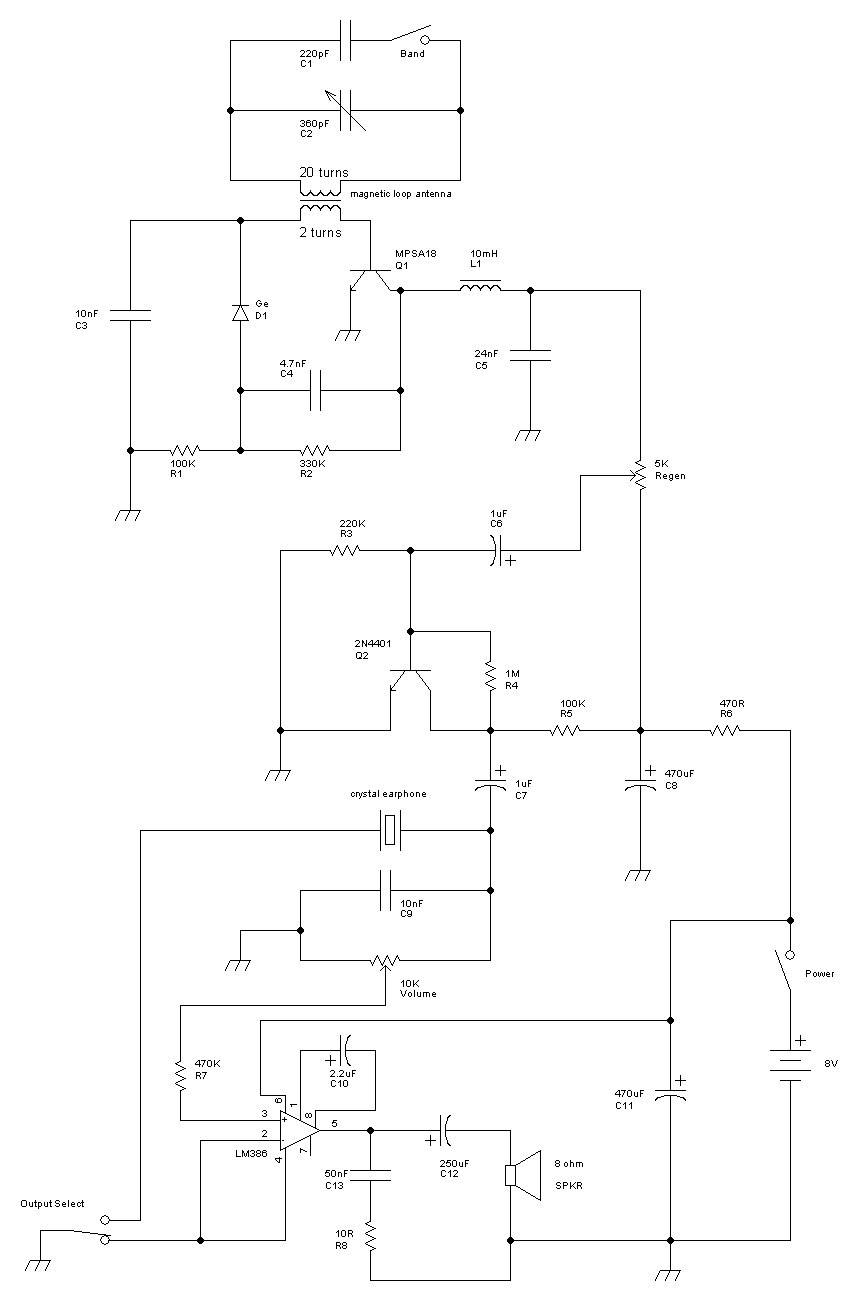
This receiver is a modification of Charles Wenzel's Two Transistor Reflex Radio. Instead of a ferrite AM loopstick antenna, a magnetic loop antenna is used, and an LM386 amplifier stage has been added to drive an 8-ohm speaker. A...
Many applications require low-frequency signal generators that can deliver high-performance, high-resolution signals. This design idea presents a circuit that generates frequencies from 0 to 1 MHz, providing sinusoidal, triangular, and square-wave outputs with frequency resolution better than 0. A...
The equation is as follows: If a circuit has a resistance of 25 ohms and a potential of 125 volts, the current drawn in this circuit would be 5 amps. This basic circuit provides a foundational understanding for the...