
Electromagnetic Field SensorCircuit Based On The uA741 IC

The Electromagnetic Field Sensor Circuit utilizes the uA741 operational amplifier to detect variations in electromagnetic fields. The circuit comprises several key components, including resistors, capacitors, and the operational amplifier itself. The uA741 is configured in a non-inverting amplifier configuration, which allows for the amplification of the small voltage signals generated by the electromagnetic field.
The input section of the circuit typically includes a sensing element, such as a coil or an antenna, which captures the electromagnetic waves. The output from this sensing element is fed into the non-inverting input of the uA741. The gain of the operational amplifier can be adjusted by selecting appropriate resistor values in the feedback loop, allowing for sensitivity tuning based on the specific application.
Additional passive components, such as capacitors, may be included to filter noise and stabilize the circuit, ensuring that only the desired frequency signals are processed. The output of the uA741 can be connected to a microcontroller or an analog-to-digital converter (ADC) for further analysis and processing of the detected electromagnetic field intensity.
This circuit finds applications in various fields, including telecommunications, environmental monitoring, and security systems, where the detection of electromagnetic fields is crucial. Proper layout and grounding practices are essential in the design to minimize interference and ensure accurate sensing performance.The following circuit shows about Electromagnetic Field Sensor Circuit Diagram. This circuit based on the uA741 IC. Features: used to sense .. 🔗 External reference
Related Circuits
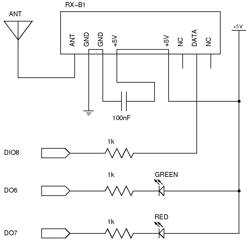
The documentation and code cleaning for the Jaycar Thermor/BIOS branded wireless weather station receiver has been completed. The code is based on the Practical Arduino weather station receiver project. The process involved analyzing the RF signal from the weather...
The sphygmomanometer can be categorized into two main types: the mercury sphygmomanometer and the electronic sphygmomanometer. The mercury sphygmomanometer is known for its accuracy, but it requires professional operation and is prone to observational errors due to subjectivity. Additionally,...
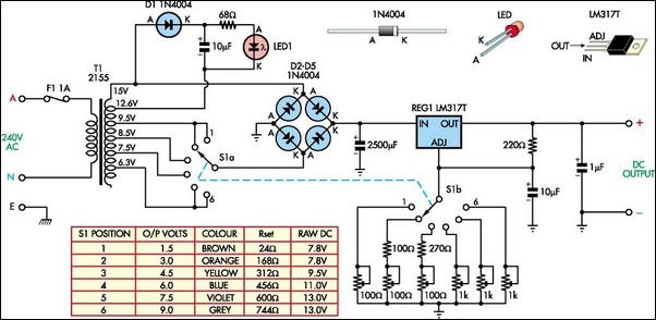
The following circuit illustrates a Battery Replacement Power Supply Circuit Diagram. This circuit is based on the LM317 integrated circuit. Features include the ability to replace... The Battery Replacement Power Supply Circuit utilizes the LM317 voltage regulator to provide a...
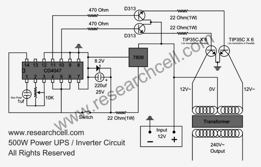
This circuit diagram features a single variable resistor utilized to adjust the frequency of a 240V AC output current. It is advisable to use a frequency meter to modify the frequency from 50Hz to 60Hz according to specific requirements....
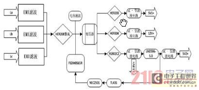
Currently, the switching power supply boasts high performance with an efficiency of 75%. The efficiency of single-scale integration switching power supplies has exceeded 90%. This advancement addresses energy concerns and enhances the performance of numerous energy-saving electrical devices. The...
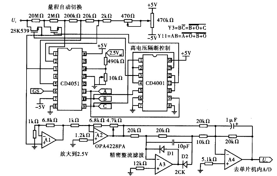
Voltage measurement is a fundamental aspect of electronic technology today, with increasing demands for accuracy and functionality in instruments. This is particularly critical when measuring signals with significant phase differences, as it is essential to ensure the accuracy of...