
Electronic combination lock with PIC

The electronic combination lock system is designed for secure access control, particularly for outdoor gates. At its core, the system operates using a microcontroller that executes the software logic for code verification and relay activation. The user inputs a numeric code via a keypad, which is interfaced with the microcontroller. Upon successful entry of the correct code, the microcontroller triggers a relay for a predetermined duration, allowing for the activation of either a power-to-open electric strike or a power-to-hold electromagnetic lock.
The relay serves as a crucial component in this circuit, as it can handle the AC voltage required by the locking mechanisms. The power-to-open electric strike operates by momentarily completing the circuit to release the lock, while the power-to-hold electromagnetic lock requires continuous power to maintain the locked state. The relay is selected based on its current and voltage ratings to ensure compatibility with the locking devices.
The system also incorporates a method for changing the access code. This feature typically requires the user to enter the current code before they can set a new one, ensuring that unauthorized users cannot easily change the access credentials. This functionality is vital for maintaining security, especially in environments where access codes may need to be updated frequently.
Additional components in the circuit may include a power supply to provide the necessary voltage for the microcontroller and relay, as well as protection elements such as diodes to prevent back EMF from the relay coil from damaging the microcontroller. Capacitors may also be employed for power smoothing, ensuring stable operation of the microcontroller during relay activation. Overall, this electronic combination lock system offers a robust solution for secure access control in outdoor applications.This is my electronic combination lock to use with an outdoor gate. The functionality is implemented in software. It turns on a relay (usually to open a door) for a few seconds if someone enters the valid code. This relay can operate a power-to-open type electric strike with a shorting contact or a power-to-hold type electromagnetic lock with a breaking contact (we need the relay because these locks usually work with AC, not DC). The code can be changed any time after entering the current code. 🔗 External reference
Related Circuits
Utilize the program to customize your experience with the woven tules of roses on a single Adobe 3 Mac card. The system's reading portion remains idle while the controller operates, as illustrated in Figure 1. This setup includes the...
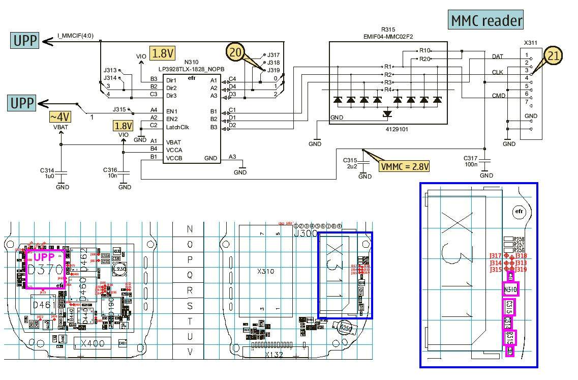
MMC corruption can be caused by a damaged MMC or a faulty memory card driver. In the Nokia 7610, there is a memory card regulator, which is an integrated circuit located near the memory card connector. Corruption of the...
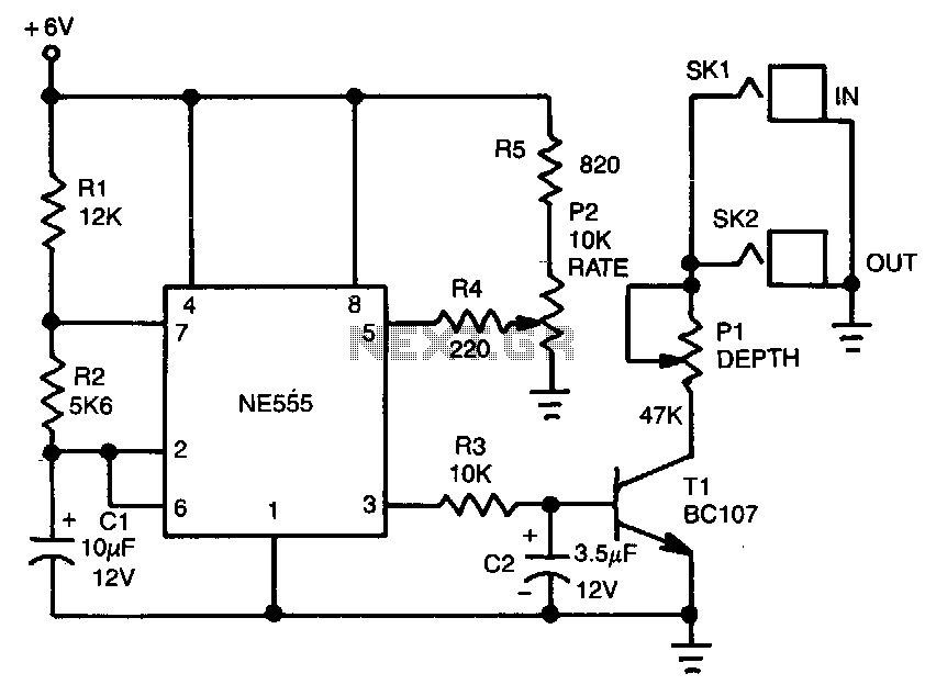
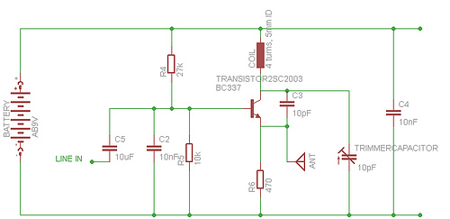
The tremolo effect is created by a repeating change in volume at a frequency typically ranging from 1 to 15 Hz. A timer generates a low-frequency square wave, which is subsequently smoothed by a simple RC integrator. This varying...
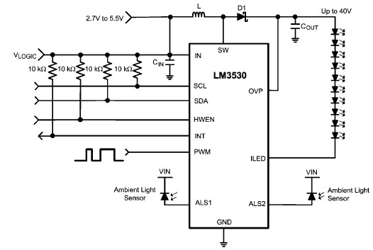
A simple white LED driver circuit can be designed using the LM3530 high-efficiency white LED driver IC, which features programmable ambient light sensing capability and an I2C compatible interface. The LM3530 LED driver can control up to 11 series...
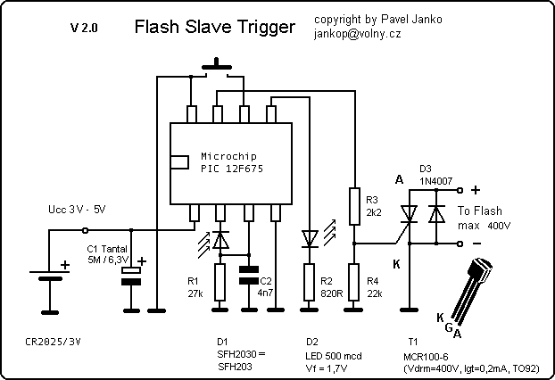
The Slave Flash Trigger is activated by pressing a push button. When activated, the indicator lamp emits one to three flickers to indicate the programmed mode. One flicker means the flash will fire with each flash, two flickers indicate...
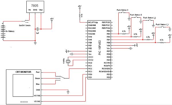
The objective of this project is to develop a device capable of outputting VGA signals to a CRT monitor to display figures, text, and characters. The project involves designing a circuit that generates standard VGA signals, which include separate horizontal...