
Electronic Telephone Ringer

The circuit's design utilizes three operational amplifiers configured as oscillators, each generating distinct frequencies that contribute to the final acoustic output. The first oscillator, with its low frequency of about 1/3 Hz, serves as a control signal for the subsequent oscillators. The triangular wave generated across the capacitor in the first oscillator is crucial for ensuring that the voltage levels at the non-inverting inputs of the op-amps are appropriately set for the oscillators to function.
The second oscillator's frequency of 13 Hz introduces a modulation effect that enriches the overall sound produced by the third oscillator. This modulation is essential for creating a more dynamic ringing sound, reminiscent of modern telephones. The use of a piezo sounder at the output stage effectively converts the electrical oscillations into audible sound waves, making the circuit suitable for applications where sound signaling is required.
Power supply considerations are also important in this design. The circuit can operate with a supply voltage ranging from 5 V to 30 V, with a notable increase in current consumption as the voltage rises. This flexibility allows for a variety of power sources to be used, making the circuit adaptable for different applications. The choice of resistor values and capacitor sizes will dictate the precise frequencies produced, allowing for further customization of the ringing sound to meet specific requirements.This circuit produces a ringing sound similar to that made by more recent telephones. It consists of three almost identical oscillators connected in a chain, each generating a squarewave signal. The frequency of each oscillator depends on the RC combination: R4 and C1 around IC1. A, R8 and C2 around IC1. B and R12 and C3 around IC3. C. The pairs of 1 00 k resistors divide the asymmetric power supply voltage (between 5 V and 30 V) so that, in conjunction with the 100 k feedback resistors (R3, R7 and R11) either one third or two thirds of the supply voltage will be present at the non-inverting inputs to the opamps. The voltage across the capacitor therefore oscillates in a triangle wave between these two values. The first oscillator is free-running at a frequency of approximately 1/3 Hz. Only when its output is high, and D1 stops conducting, can the second oscillator run. The frequency of the second oscillator is about 13 Hz, and optional LED D3‚ashes when it is running. When the output of the second oscillator is low, the third is allowed to run. The frequency of the third oscillator is around 1 kHz, and this is the tone that is produced. The second oscillator is not absolutely necessary: its function is just to add a little modulation to the 1 kHz tone.
A piezo sounder is connected to the output of the third oscillator to convert the electrical signal into an acoustic one. The current consumption of the circuit is just under 1mA with a 5V power supply, rising to about 1. 65mA with a supply voltage of 15 V. 🔗 External reference
Related Circuits

An electronic decorative peacock consists of 10 light-emitting diodes (LEDs), each of which contains multiple LEDs arranged in the tail of the peacock model. The light emission drive circuit operates the fan-shaped LEDs in a cyclic manner, emitting light...
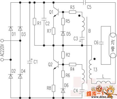
The saving lamp circuit features two main types: glass cover and exposed. The glass cover variants include three series: spherical, cylindrical, and processing types. The first two series consist of four variations: transparent, carved, engraved, and white. These lamps...

The schematic illustrates the design of a circuit that measures the resistance of the skin and transforms it into a functional switching signal. This circuit typically employs a resistive sensor, often referred to as a skin resistance sensor or galvanic...
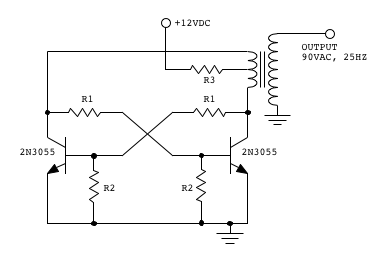
Make two telephones ring on stage. This involves sending a signal down a line to the phones. An old telephone exchange system was initially sought but not found. Several circuit ideas have been discovered, but the goal is to...
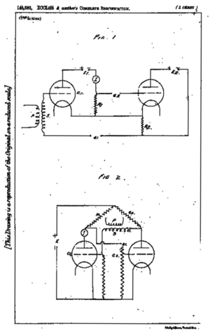
A flip-flop is a bistable multivibrator. It is a circuit that has two output states and is switched from one to the other by means of input signals. A flip-flop serves as a fundamental building block in digital electronics, primarily...

The electronic schematic of the Light Detector Robot can be divided into three main components: the sensor, the microcontroller, and the DC motor driver. The light sensor utilized in this design is a Light Dependent Resistor (LDR), which alters...