
Electronic thermostat circuit

The thermostat circuit is designed to control the temperature of a system by switching between different power levels. The circuit includes a DIP switch (SA) that allows the user to select between three operational modes: off, low power (Lo), and high power (Peru HL).
In the low power mode, when the switch is set to Lo, the circuit allows 220V AC to flow through diodes VD4 and VD56. These diodes serve as rectifiers, converting the AC voltage to a pulsating DC voltage through half-wave rectification. This process effectively reduces the voltage supplied to the load (RL), which is crucial for applications requiring lower heat output. The reduction in voltage results in a significant decrease in the power dissipated by the load, thereby lowering its temperature.
The circuit's design ensures that in the high power mode (Peru HL), the load receives the full 220V AC, allowing for maximum heating capability. The off position completely disconnects the load from the power supply, ensuring that no current flows and the load remains inactive.
This thermostat circuit is commonly used in heating applications where precise temperature control is necessary. By utilizing the DIP switch to select the desired power level, users can effectively manage the thermal output of the system, ensuring optimal performance and energy efficiency.Thermostat electric circuit as shown in FIG. It points to off (off), Lo (low power), Peru HL (high power) third gear. When DIP switch SA to Lo gear, 220V electricity through the diode VD4, VD56 added to the load RL ends; half-wave rectified by a diode so that RL was significantly lower than when the operating voltage 220v straight, so RL temperature drops.
Related Circuits
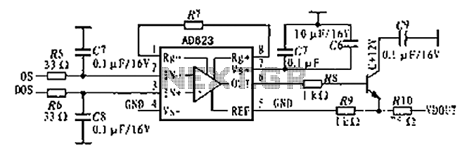
The AD623 is an integrated 3-way amplifier that can operate with either a single or dual supply. It features high common-mode rejection ratio (CMRR) and low voltage drift, along with programmable gain control via an external resistor. All components...
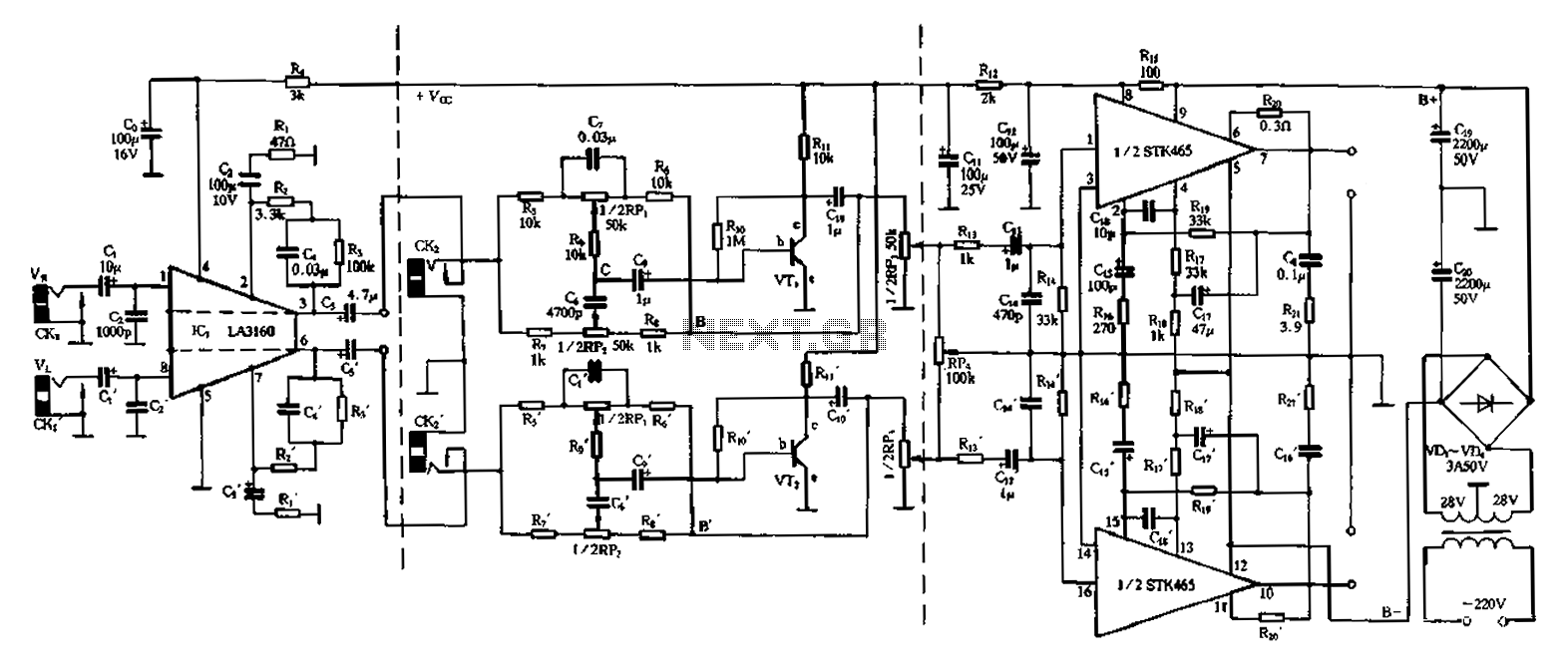
The 50W is a two-channel amplifier featuring a preamplifier and tone control based on the LA3160 integrated circuit. Its external components include the input preamplifier, with C1 serving as the input coupling capacitor. The circuit incorporates a high-frequency bypass...
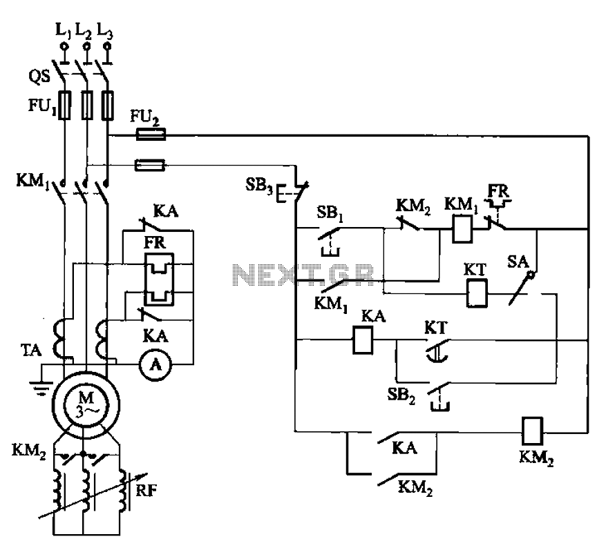
The circuit shown in Figure 3-164 can operate in both manual and automatic modes. During startup, the normally closed contact of relay KA is shorted, which affects the heating element to avoid prolonged startup times that could lead to...
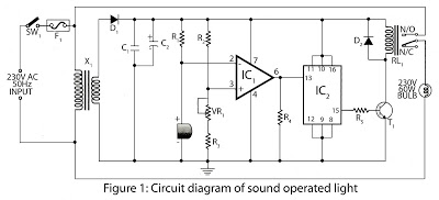
This is a hobby circuit designed for electronics enthusiasts that can turn on and off devices such as lights, fans, and radios in response to the sound of a clap. The sound is detected by a small microphone, which...
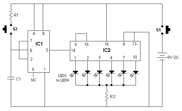
It is advisable to enclose this circuit in a box and label each LED with numbers from 1 to 6. When switch S1 is momentarily pressed, one of the six LEDs will illuminate, with the number corresponding to the...
Infrared remote controls are using a 32-56 kHz modulated square wave for communication. These circuits are used to transmit a 1-4 kHz digital signal (OOK modulation) through infra light (this is the maximum attainable speed, 1000-4000 bits per sec)....