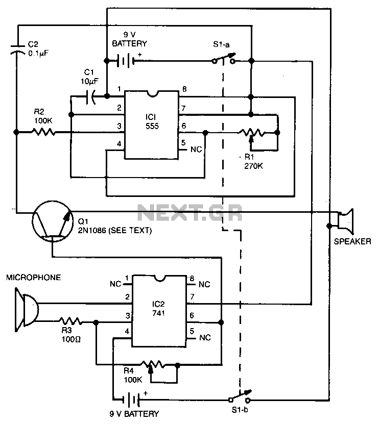
Electronic-voice-substitute

The 555 timer operates as a tone generator configured in astable mode. Its output at pin 3, which is a square wave, is converted into a triangle wave using resistor R1 and capacitor C2. The pitch of the generated voice is controlled by the RL transistor Q1, which can be a 2N1086, 2N1091, or any equivalent NPN germanium type. The sounds produced are amplified by the 741 operational amplifier, and the output from the IC drives the transistor into saturation. When the transistor is in saturation, the triangle wave can reach the speaker, allowing the generated voice to be heard.
The circuit utilizes a 555 timer in astable mode to produce a continuous square wave output, which is fundamental for generating audio tones. The frequency of oscillation is determined by the values of the resistors and capacitors connected to the 555 timer. In this case, resistor R1 and capacitor C2 play crucial roles in shaping the waveform from a square wave to a triangle wave. The triangle wave is essential for creating a smoother sound output, which is more pleasant to listen to compared to a harsh square wave.
The pitch of the sound is modulated by adjusting the RL transistor Q1, which can be selected from several NPN germanium transistors such as the 2N1086 or 2N1091. The choice of transistor affects the gain and frequency response of the circuit, influencing the overall sound quality.
The 741 operational amplifier is employed to amplify the audio signal generated by the 555 timer. This amplifier increases the signal strength to a level suitable for driving a speaker. The output from the 741 is designed to saturate the Q1 transistor, ensuring that it operates in a fully on state, which is crucial for allowing the triangle wave signal to pass through effectively to the speaker.
When Q1 is in saturation, it provides a low-resistance path for the triangle wave signal, enabling it to reach the speaker. This configuration allows the generated audio tone to be reproduced audibly, resulting in the desired voice output. The careful selection of components and their configuration in this circuit is essential for achieving the intended audio performance and tonal quality.The 555 acts as the tone generator configured in the astable mode. Its pin 3. square-wave output is transformed into a triangle wave by Rl and C2. The voice"s pitch is controlled by RL Transistor Ql can be 2N1086, 2N1091, or any other equivalent npn germanium type. Sounds are amplified by the 741, and the IC"s output drives the transistor to saturation. When the transistor is in the saturated state, the triangle wave is able to reach the speaker, and your new voice can be heard.