
electronics and communication projects

An active antenna circuit designed for AM, FM, and shortwave (SW) reception is also presented. This active antenna can be compared to a 20 to 30-foot wire antenna on the shortwave band and is suitable for receivers that utilize untuned wire antennas, including inexpensive models and car radios. The inductor L1 can be selected based on the specific application.
Another circuit described is a medium wave (MW) active antenna, which amplifies the input from a telescopic whip antenna. This preamplifier is intended for the medium waveband, covering frequencies from approximately 550 kHz to 1650 kHz. The required tuning voltage ranges from 1 to 12 volts and can be sourced from a 10k potentiometer connected to a 12-volt power supply. The gain control, RV1, allows for the amplification of weak signals or attenuation of strong signals. The control voltage is applied to gate 2 of TR1, a dual-gate MOSFET, while the signal voltage is applied via gate 1.
A method for designing multiple order all-pole bandpass filters by cascading second-order sections is also discussed. Linear Technology presents two methods aimed at simplifying the mathematics involved in filter design using tabular methods. The document assumes no prior experience in filter design, allowing for the implementation of high-quality filters using techniques not previously documented. Examples utilize devices from LTC's Switched Capacitor filter family, including LTC1060, LTC1061, and LTC1064, covering both Butterworth and Chebyshev bandpass filter designs.
In low-noise analog circuits, a high-gain amplifier is essential at the input stage to enhance the signal-to-noise ratio (SNR). The input signal level dictates the necessary input-stage gain, with low-level signals requiring the highest gain. It is also standard practice in low-noise analog signal processing to narrow the circuit's bandwidth to pass only the useful input signal spectrum.
A bandpass filter, utilizing a single operational amplifier, allows a range of frequencies to pass while rejecting those outside the defined upper and lower limits of the passband. The passband extends from a frequency below the center frequency to one above it, where the output voltage drops to approximately 70% of the output voltage at the center frequency.
The three-amplifier implementation of the state-variable filter provides second-order responses for bandpass, highpass, and lowpass configurations. The circuit's strength lies in its bandpass response, where achieving high gain and high Q is straightforward, making it suitable for applications where selectivity is critical.
Additionally, an ordinary low-cost line transformer can be effectively utilized as an isolation transformer, capable of passing millihertz signals, thereby providing a cost-effective solution for signal isolation in various electronic applications.If you want to do the ground loop elimination in audio path, you have to cut the galvanic connection but pass the whole audio range. The simplest and most common way to do the isolation is use audio transformer which is ment for audio use.
Transformers for audio use have some problems like distorted bass response and attenuating in high-frequency response. Basically a transformer slows down upper frequencies and allow the low frequencies to pass first, creating what we perceive as a "fat/warm" tone. Inadequate frequency response on the low end (rolloff at like 20Hz), causes low frequencies to be "slowed", allowing the upper frequencies to be heard first, this is perceived as "barky/ brittle".
High-quality audio transformers cover whole audio band with good response, but those are quite expensive. (Schematic / circuit added 10/05). AM/FM/SW Active Antenna : This circuit shows an active antenna that can be used for AM, FM, and shortwave SW.
On shortwave band this active antenna is comparable to a20 to30 foot wire antenna. This circuit uses receivers that use untuned wire antennas, such as inexpensive units and car radios. L1 can be selected for application (added 4/02) MW Active Antenna : This circuit is designed to amplify the input from a telescopic whip antenna.
The preamplifier is designed to cover the medium waveband from about 550Khz to 1650Khz. The tuning voltage required is 1 to 12 volts and can be obtained from a 10k potentiometer connected to the 12 Volt power supply. RV1 is the gain control allowing weak signals to be amplified or strong signals to be attenuated. The control voltage is applied to gate 2 of TR1, a dual-gate MOSFET, the signal voltage applied via gate 1;.
(added 10/05) A Simple Method of Designing Multiple Order All Pole Bandpass Filters by Cascading 2nd Order Sections : AN27A Linear Technology Presents two methods of designing high quality switched capacitor bandpass filters. Both methods are intended to vastly simplify mamatics involved in filter design by using tabular methods.
The text assumed no filter design experience but allows high quality filters to be implemented by techniques not presented before in literature. The designs are implemented by numerous examples using devices from LTC`s SwitchedCapacitor filter family: LTC1060, LTC1061, and LTC1064.
Butterworth and Chebyshev bandpass filters are discussed. Bandpass Filter Features Adjustable Q and Constant Maximum Gain : 03/3/05 EDN-Design Ideas / (added 5/05) In low-noise analog circuits, a high-gain amplifier serves at input to increase SNR. The input signal level determines input-stage gain; low-level signals require highest gain. It is also standard practice in low-noise analog-signal processing to make circuit`s bandwidth as narrow as possible to pass only useful input-signal spectrum.
Bandpass Filter Single Opamp : A band pass filter passes a range of frequencies while rejecting frequencies outside upper and lower limits of passband. The range of frequencies to be passed is called passband and extends from a point below center frequency to a point above center frequency where output voltage falls about 70% of output voltage at center frequency.
(added 5/02) Dpps Program Key Parameters of Bandpass Filter : 12/12/02 EDN Design Ideas / (added 12/04) The three-amplifier implementation of the state-variable filter in Figure 1 provides for second-order bandpass, highpass, and lowpass responses. The strength of the circuit, however, is in the bandpass response (VOUT/VIN), in which it`s easy to achieve high gain (G) and high Q.
These two characteristics are important in applications in which selectivity is a key parameter in the filter. Isolation Transformer Passes Millihertz Signals : 08/04/94 EDN-Design Ideas / (Electronic Circuit diagram added 03/03) You can successfully use an ordinary low-cost line transformer as an isolation transformer in
🔗 External reference
Related Circuits

The clock pulses from the 555 astable circuit are sent into the 4017 decade counter. Each output becomes high in turn as the clock pulses are received. Appropriate outputs are combined with diodes to supply the amber and green...
The EUA2032 is a high-efficiency, 2.5W mono class-D audio power amplifier. A newly developed filterless PWM modulation architecture further reduces EMI and THD+N, as well as eliminates the LC output filter, thereby reducing the external component count, system cost,...
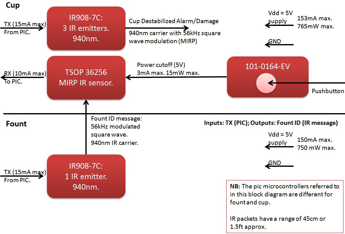
The founts must notify the server when the cup is taken from the fount or when the opponent's cup is poured into the team's cup. The implementation of the actual pouring action is at the discretion of the team....
This document discusses the use of small microcontrollers, such as those from the PIC and Atmel series, which typically operate at 5V and require less than 100mA for complete system functionality. Some PICs can function at lower voltages, such...
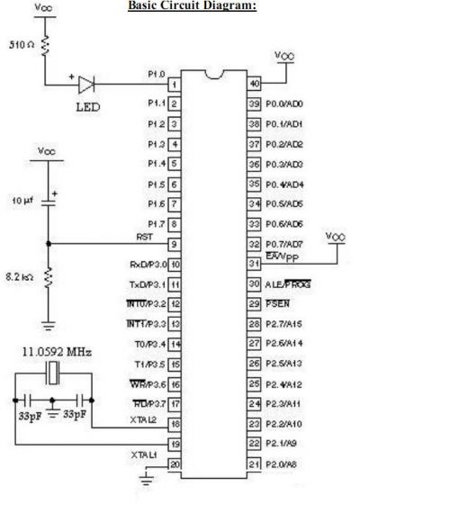
Microcontrollers and Microprocessors - The 8051 Projects Page! Discover comprehensive information on 8051 projects here. Everything you wanted to know about 8051 projects is available. The 8051 microcontroller, developed by Intel in the 1980s, is a widely used microcontroller in...
Instructions for supervising landscaping projects recommended by satellite relay protection and automatic safety devices. This includes information on the general table for three remote programs related to petrochemical engineering construction, electrical transmission, and the intelligent implementation of community weak...