
Electronics Thermometer with description

The electronic thermometer circuit utilizes a silicon diode as a temperature sensor due to its reliable characteristics and linear response to temperature changes. The chosen diode, 1N4148, is known for its low forward voltage drop and fast switching capabilities, making it suitable for precise temperature measurements. The operational amplifier serves as a critical component in converting the small voltage changes from the diode into a more significant output voltage that can be easily read and interpreted.
The configuration of the operational amplifier is such that it operates in a non-inverting mode, allowing for amplification of the voltage signal derived from the diode. The resistors R1 and R2, along with the variable resistor VR1, form a voltage divider network that establishes a reference voltage at the non-inverting input of the operational amplifier. This setup ensures that the output voltage from the amplifier is a linear representation of the temperature sensed by the diode.
The feedback loop created by the diode D1 allows for continuous adjustment of the output voltage based on real-time temperature readings. As the temperature varies, the corresponding change in voltage drop across the diode is fed back into the operational amplifier, which adjusts its output accordingly. This dynamic response enables the thermometer to maintain accuracy across its extensive measurement range.
For practical implementation, the output of the operational amplifier can be connected to an analog or digital display for easy reading. Additionally, calibration of the thermometer may be necessary to ensure precision across the specified temperature range. This circuit design is not only effective for medical applications but can also be adapted for industrial temperature monitoring, research, and other fields requiring accurate temperature measurements.Clinical thermometer is only used by doctor because it is difficult to read. Here is a circuit of electronics thermometer used to measure vast range of temperature from -200C to 1250C. This single circuit electronics thermometer can be used to measure differenttemperature. The wide range of temperature measurement made this circuit versatile. This entire circuit Electronics thermometer is built and fabricated around silicon diode D1 (1N4148) and Operational amplifier IC. Diode D1 is used as temperature sensor, temperature determined the value of voltmeter drop across diode i.
e. at room temperature voltage drop is 0. 7V and is reduce by about 2mV/0C. For temperature-to-voltage conversion in electronics thermometer an operational amplifier is used. The input voltage at non-inverting pin 3 of IC1 is fixed by VR1, R1, & R2 where sensor diode D1 forms a feedback path. The output of IC1 is directly depends on the voltage across the diode. 🔗 External reference
Related Circuits

This thermometer utilizes an NTC thermistor (RIO) to generate a DC voltage that decreases with temperature, which in turn drives an integrated circuit (IC) that activates one of the 16 LEDs based on this voltage. R1 is a light-dependent...
The power supply has been simplified. Power transformers and rectifiers have been omitted, and some components from the MOSFET voltage regulator circuits have been removed, including 1N5242 zener diodes between the source and gate and 10k resistors in series...
Over 1400 top electronics projects and electronic circuits with photos, datasheets, and easy-to-read schematics, along with explanations of how they work and how to build them. The collection comprises a vast array of electronics projects suitable for enthusiasts and professionals...
This circuit is designed for precise measurement of temperature in degrees Celsius. It features a transmitter section that converts the output voltage from a temperature sensor, which is proportional to the temperature being measured, into frequency. The resulting frequency...
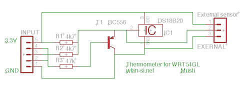
This circuit is a simple dual simplex to half-duplex driver for 1-wire devices. However, it does not function with all devices, as some may draw excessive current. It was specifically designed and tested for the DS18B20+ 1-wire digital thermometer....
The thermistor network specified eliminates the need for a linearity trim at the expense of accuracy and operational range. The thermistor network is designed to provide a simplified approach to temperature measurement and compensation by negating the requirement for linearity...