
Emitted by the two co-polar amplifier broadband amplifier practical

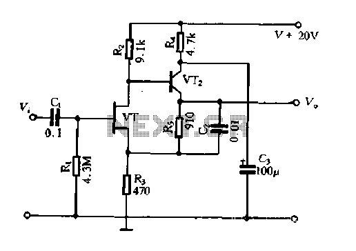
The two-stage common emitter amplifier is designed to provide significant amplification over a broad frequency range, making it suitable for applications in communication systems. The use of capacitors for coupling allows for efficient signal transfer between stages while blocking DC components, ensuring that only the AC signal is amplified.
The emitter decoupling capacitor, C4, plays a crucial role in stabilizing the amplifier's performance by bypassing AC signals to ground, which minimizes the impact of negative feedback that could otherwise reduce gain. This feature is particularly important in high-frequency applications where maintaining signal integrity is essential.
The -15V power supply is critical for the operation of the amplifier, providing the necessary biasing for the transistors used in the common emitter configuration. The inductor (10 µH) is strategically placed in the circuit to improve the stability of the power supply by reducing high-frequency noise and ripple.
Additional components, such as C3 and R11, serve as low-pass filters, effectively attenuating any unwanted high-frequency noise present in the power supply. C2 may also act as a bypass capacitor, further smoothing out the power supply voltage and ensuring stable operation of the amplifier.
Overall, this two-stage common emitter amplifier circuit is well-suited for applications requiring high gain and wide bandwidth, and its design incorporates essential elements for signal integrity and power supply stability.Emitted by the two co-polar amplifier broadband amplifier practical It is shown by the two-stage common emitter amplifier very practical wideband amplifier. Between the input a nd output capacitors are used, and is coupled way, C4, cs is the emitter decoupling capacitor to eliminate AC negative feedback, enhance communication signal amplification ability, -15V power supply connected to the inductor (10 yH) and It6, C3, Rii, island, C2, etc. are filters used to filter the power supply ripple.
Related Circuits
A compact power amplifier that delivers high-quality sound. It incorporates a NE5534 operational amplifier, known for its excellent performance, capable of handling low loads, providing high speed, and exhibiting low distortion. Additionally, it features two V-MOSFET transistors at the...
The Field Effect Transistor (FET) exhibits a high input impedance, allowing the construction of high input impedance amplifiers. However, as a FET amplifying device, the distributed capacitance and the Miller effect significantly increase input capacitance at high frequencies. Furthermore,...
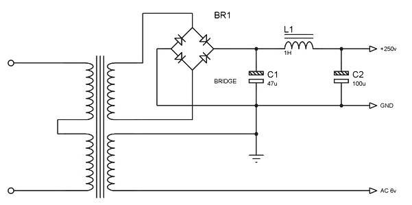
Power supply for a simple high-quality tube amplifier class A power supply. This power supply circuit is part of a series of simple high-quality tube amplifier class "A" designs. It may also be applicable to other devices. Detailed explanation:...
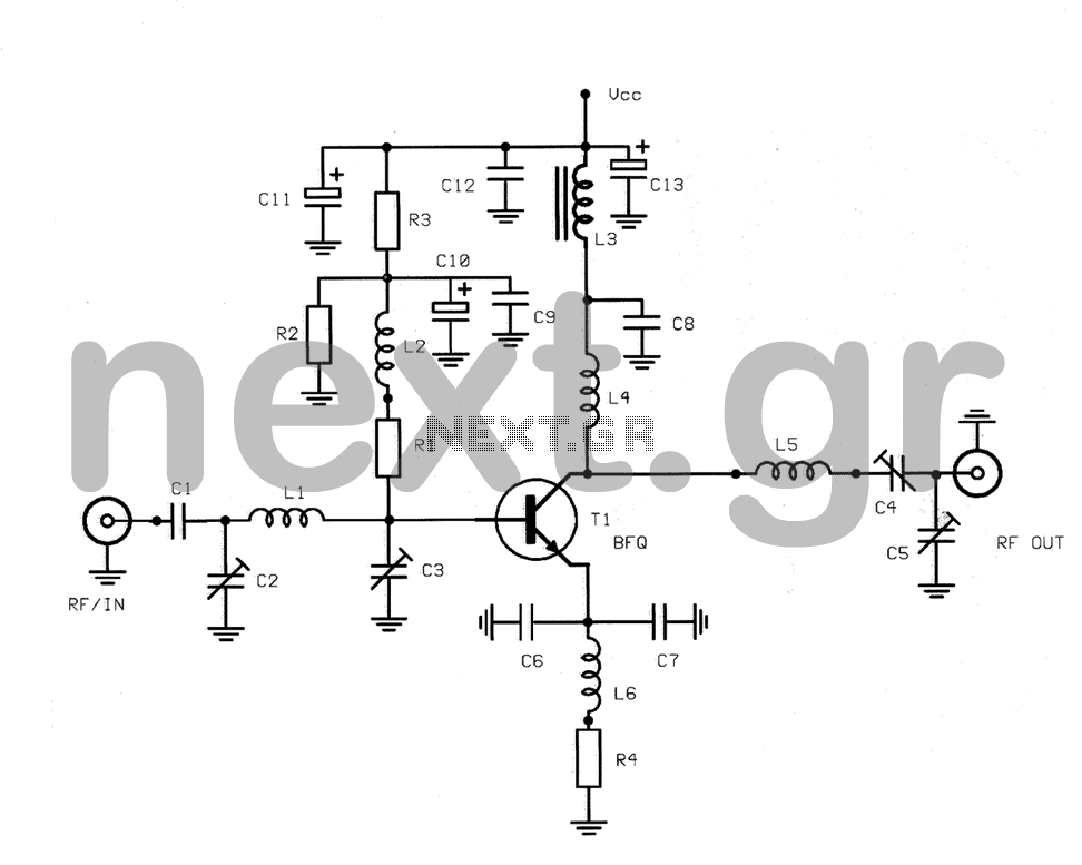
This structure is a radio frequency (RF) amplifier designed for small UHF TV transmitters, operating within the UHF channel range of 450-800 MHz. The amplifier enhances video signals in this frequency range and operates in Class A, utilizing the...
This circuit diagram represents an ECM Mic Preamplifier. It is a microphone amplifier compatible with Electret Condenser Microphones (ECM). The preamplifier exhibits an excellent dynamic range, capable of handling audio levels from a whisper to a scream; however, caution...
A popular project among microcontroller enthusiasts is to construct a radio-controlled clock. Compact receiver boards are available, equipped with a pre-tuned ferrite antenna, which can receive and demodulate the DCF77 time signal broadcast from Mainflingen, Germany. The DCF77 signal...