
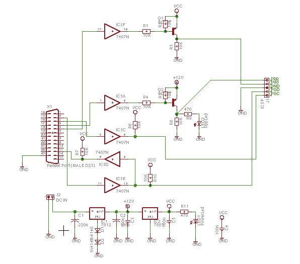
Equipment controller with PC

Lots of ways to control the hardware can be implemented using software. In C/C++ one can use the outportb(portno,value) function where portno is the parallel port address (usually 378hex for LPT1) and 'value' is the data that is to be sent to the port. For a value=0 all the outputs (D0-D7) are off. For value=1 D0 is ON, value=2 D1 is ON, value=4, D2 is ON and so on. eg. If value=29(decimal) = 00011101(binary) ->D0,D2,D3,D4 are ON and the rest are OFF.
The circuit utilizes a standard 25-pin parallel printer port, commonly found on older PCs, for the control of multiple devices. The primary function of the circuit is to enable control of up to eight devices (or equipment) through the use of digital output lines D0 to D7. Each output line corresponds to a specific pin on the parallel port, where pin 2 is assigned to D0, pin 3 to D1, and so forth up to pin 9 for D7.
The interface circuit is designed with an opto-coupler, which serves as an interface between the computer's parallel port and the relay driver circuitry. This configuration is crucial as it provides electrical isolation, protecting the PC from any high voltages or currents that may be present in the controlled devices. The opto-coupler operates by allowing the control signal from the parallel port to activate an internal LED, which in turn triggers a phototransistor to close the relay circuit.
In terms of software control, the implementation can be done using C or C++ programming languages. The `outportb` function is utilized to send data to the parallel port, where the first parameter is the port address, typically 378h for LPT1, and the second parameter is the value representing the state of the outputs. The binary representation of the value determines which outputs are activated; for instance, a value of 29 in decimal translates to the binary 00011101, which means that D0, D2, D3, and D4 are turned ON while D1, D5, D6, and D7 remain OFF.
This setup allows for flexible control of various devices, such as motors, lights, or other electronic components, by simply adjusting the output values sent to the parallel port. The circuit can be expanded by replicating the interface circuit for each additional device, ensuring that all eight outputs can be independently controlled. Here is a circuit for using the printer port of a PC, for control application using software and some interface hardware. The interface circuit along with the given software can be used with the printer port of any PC for controlling up to eight equipment .
The interface circuit shown in the figure is drawn for only one device, being controlled by D0 bit at pin 2 of the 25-pin parallel port. Identical circuits for the remaining data bits D1 through D7 (available at pins 3 through 9) have to be similarly wired.
The use of opto-coupler ensures complete isolation of the PC from the relay driver circuitry. Lots of ways to control the hardware can be implemented using software. In C/C++ one can use the outportb(portno,value) function where portno is the parallel port address (usually 378hex for LPT1) and 'value' is the data that is to be sent to the port. For a value=0 all the outputs (D0-D7) are off. For value=1 D0 is ON, value=2 D1 is ON, value=4, D2 is ON and so on. eg. If value=29(decimal) = 00011101(binary) ->D0,D2,D3,D4 are ON and the rest are OFF. 🔗 External reference
Related Circuits
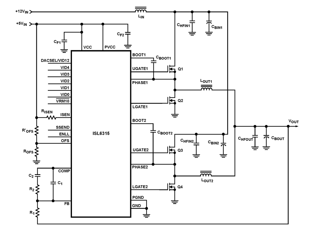
The ISL6315 two-phase PWM control integrated circuit (IC) offers a precise voltage regulation system capable of handling advanced loads ranging from 60A to 80A. Multiphase power conversion represents a significant shift from traditional single-phase converter configurations, which are increasingly...
National Instruments Multisim now features microcontroller unit co-simulation capabilities, enabling the inclusion of a microcontroller, programmed in assembly or C code, within SPICE-modeled circuits. The MCU functionality in Multisim allows students, educators, and professional users to program MCUs in...
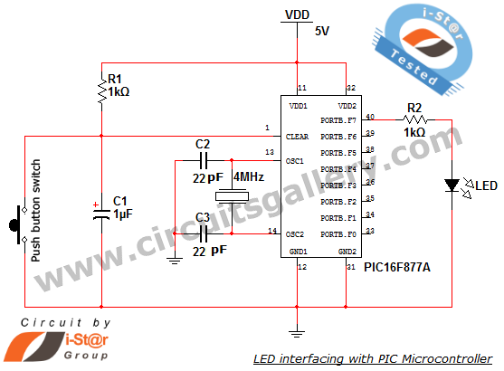
How to interface an LED with Microchip's PIC microcontroller. Connecting LEDs to a PIC microcontroller is fundamental for microcontroller development. This guide presents a simple embedded program for the PIC 16F877A to interface LEDs, making it suitable for beginners...
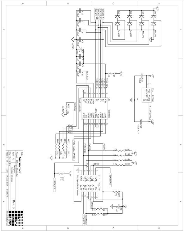
The following are detailed schematics for the QScreen Controller. The QScreen Controller integrates an embedded computer utilizing the 68HC11 microcontroller, along with a touch panel and an LCD (liquid crystal display) graphic user interface (GUI) that is well-suited for...
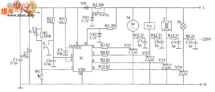
The industrial fuel oil furnace controller circuit consists of a power supply circuit, a testing and ignition control circuit, and a control implementation circuit, as illustrated in the accompanying diagram. The power supply circuit includes a step-down capacitor (C6),...
Schaer is a generic programmer circuit capable of uploading and downloading firmware to and from several electronic devices, such as microcontrollers. The Schaer programmer circuit is designed to facilitate the transfer of firmware between a host computer and various electronic...