
experiments with 741 operational amplifier

The 741 operational amplifier is a widely used device in various analog applications due to its versatility and ease of use. In this context, the dark detector circuit leverages the characteristics of the LDR, which exhibits a decrease in resistance in the presence of light. Conversely, in low-light conditions, the resistance increases significantly. This property is essential for the operation of the dark detector.
The circuit configuration employs the 741 op-amp in inverting mode, which allows for the comparison of the voltage levels. The LDR is connected in such a way that its resistance change leads to a corresponding change in the voltage at the inverting input (pin 2) of the op-amp. A reference voltage is applied to the non-inverting input (pin 3), which serves as a threshold level. When the voltage at pin 2 exceeds the reference voltage at pin 3, the op-amp output at pin 6 transitions to a high state, indicating a dark condition.
In addition to the LDR, the circuit may include a phototransistor and a photodiode to enhance sensitivity and response time. The phototransistor can amplify the current generated by the photodiode when exposed to light, further improving the circuit's performance in detecting changes in ambient light levels.
For practical implementation, it is essential to consider the power supply requirements of the 741 op-amp and ensure that the components are correctly rated for the intended application. Additionally, appropriate resistors may be used to set gain and adjust sensitivity, allowing for fine-tuning of the dark detection threshold.
Overall, this 741 operational amplifier-based dark detector circuit showcases the fundamental principles of analog signal processing and serves as a valuable project for understanding light sensing applications in electronics.This versatile 741 operational amplifier module can be used for making a dark detector using an LDR, a photo transistor and a photo diode. The amplifier has been configured in inverting mode. It compares the change in voltage at pin 2 with the reference voltage at pin 3 and gives output at pin 6 accordingly.
A general calculation and working of similar project has been explained on buildcircuit. com. CLICK HERE for the project. 🔗 External reference
Related Circuits
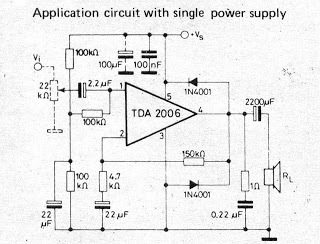
The video amplifier depicted in the diagram is a well-established design that is both simple and effective. However, there is a risk of damaging the transistors if the potentiometers (black level and signal amplitude) are set to their extreme...
A small amplifier IC circuit has been compiled. This circuit is part of an older series and is categorized as a simple OTL (Output Transformer-Less) circuit. The presented small amplifier IC circuit is designed for applications where compact size and...
The input stage is comprised of both halves of a 6SL7 octal dual hi-mu triode in a differential amp configuration with a 1mA constant current cathode load. Field-effect (constant-current) diodes are used for simplicity. The differential amp approach was...
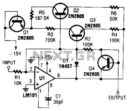
This operational amplifier circuit utilizes resistor and transistor feedback elements to function as a nonlinear amplifier. The resistors R4 and R6 can be adjusted to modify the breakpoints as needed. This operational amplifier circuit is designed to operate within the...
To commemorate the hundredth design posted on this website and to meet the requests of numerous correspondents desiring a more powerful amplifier than the 25W MosFet, a 60 - 90W high-quality power amplifier design is presented. The circuit topology...
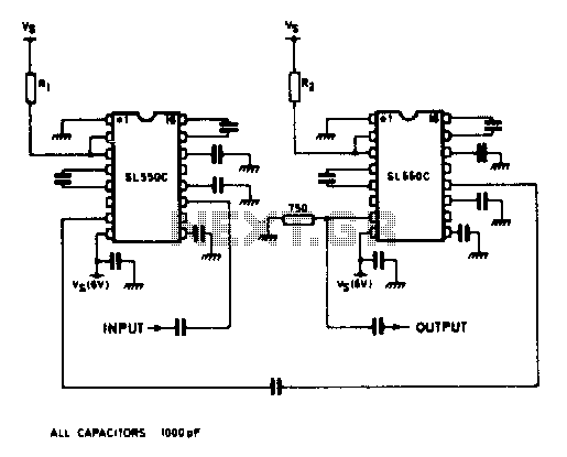
A wideband high gain configuration using two SL550s connected in series. The first stage is connected in a common emitter configuration, while the second stage is a common base circuit. Stable gains of up to 65 dB can be...