
filtering noisy power signal

Another issue is the low switching frequency of the boost converter, which is currently set at 10 kHz. This frequency is inadequate for achieving good audio performance. The datasheet indicates that the pulse frequency decreases with increasing load current, and this particular boost converter has a fixed 'on' time with variable 'off' time to adjust the duty cycle. Given the relatively low current draw of the circuit, the pulse frequency remains low. A regulator utilizing pulse width modulation (PWM), with a constant pulse frequency and variable 'on' time, would be preferable for regulating output voltage. Alternatively, a higher frequency regulator of a similar design should be considered. A frequency of 100 kHz would be more manageable for filtering, both from the power supplies and the audio path, and would be inaudible even if some noise were to pass through.
In experiments, adding a large 100 µF capacitor to the microphone has proven effective in reducing ripple. While this serves as a viable backup solution, the goal is to avoid its necessity, as the new higher frequency operation should allow for the use of a smaller capacitor. Future plans include designing a custom microphone sensor that incorporates these recommendations. A final note of interest is that the Max756 exhibited poor efficiency at low current loads, prompting a switch to a TI boost converter, which nearly doubles the efficiency at low loads when powered from a single lithium polymer cell. Measurements indicated a current draw of 52 mA with the Max756 compared to 27 mA with the TI converter.
To enhance the performance of the microphone powered by the boost converter, the following schematic modifications are suggested:
1. **Power Supply Filtering**: Implement a larger capacitor (10 µF) in parallel with the existing 100 nF bypass capacitor. This addition will help smooth out voltage fluctuations and reduce ripple.
2. **Series Inductor/Resistor**: Introduce a resistor or inductor in series with the Vcc line leading to the microphone breakout board. This will help in further isolating the microphone power supply from noise present in the main power supply.
3. **Switching Frequency Optimization**: Consider switching to a boost converter with a higher switching frequency, ideally around 100 kHz. This change will facilitate better filtering capabilities and reduce the impact of noise on the audio signal.
4. **Custom Microphone Sensor Development**: In future designs, ensure that the microphone sensor incorporates effective filtering and power management strategies to minimize ripple and enhance audio quality.
5. **Efficiency Considerations**: Evaluate and compare different boost converters to identify options that provide better efficiency for low current applications, thereby reducing overall power consumption and improving system performance.
These recommendations aim to address the ripple issues experienced in the current design and improve overall audio performance in applications requiring microphone integration.Previously I used a linear regulator, now I use Max756 ( ) boost converter. I`m seeing 0. 1 - 0. 3V output ripple in the current. The Max756 datasheet says I should expect about 50 mA ripple. So my power is a little noisier than expected, but my real problem is when powering a microphone (plugged into sensor1) I see 2. 4V of ripple. This just isn`t acceptable for my needs. Here is my scope output (blue is power signal and yellow is mic output while it`s quiet): First, your microphone amplifier has a gain of 100 and sees ripple on the power supply exactly the same as a signal from the microphone. You need to heavily filter the supply going to the microphone and amplifier circuit. First thing, add a bigger capacitor (maybe 10 uF) in parallel with the 100 nF bypass capacitor on the breakout board.
Then add a resistor or inductor in series with the Vcc line from the main board to the microphone breakout board. Your second problem is that your switch frequency is too low. The switching frequency is 10 kHz - you are just never going to get good audio performance with a 10 kHz switcher anywhere nearby.
If you look at the data sheet, the pulse frequency drops with load current. It looks like this particular boost converter has a fixed duration `on` time, and changes the off time to vary the duty cycle as needed. Your circuit is drawing relatively low current so the pulse frequency is very low. You would prefer to have a style of regulator that works by pulse width modulation: the pulse frequency is constant, but the `on` time is varied to regulate the output voltage.
Alternately, look for a regulator of the same style that works at a higher frequency under your actual load current. 100 kHz is easier to filter from the supplies, easier to filter from the audio path, and inaudible even if a bit makes it through.
Thanks for the feeback ejeffrey. I have experimented with putting a fairly large 100 uF cap on the microphone and that does fix it. I can do that as a backup, but hopefully it won`t be needed and at the very least the new higher frequency will let me us a much smaller cap on the microphone. I do plan to make my own microphone sensor someday and I`ll be sure to incorporate what was mentioned here.
One last note that might be helpful for others. The thing that finally made me make this fairly big change late in the design was the max756 was giving me terrible efficiency at my low current loads. I did some experiments and the TI boost converter gives me nearly twice the efficiency of the max chip at my low loads from a single cell lithpoly.
I measured 52 mA with the max chip and 27 mA with the TI chip. 🔗 External reference
Related Circuits
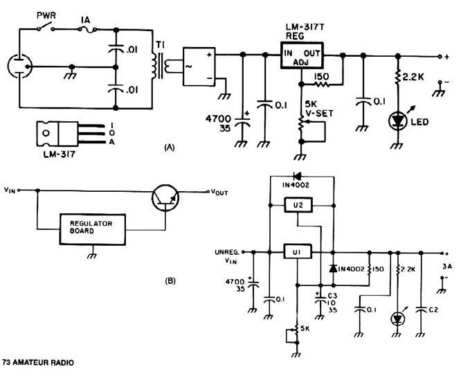
Universal Power Supply Module 3V-30V power supply. Refer to the specified page for an explanation of the related circuit diagram. This power supply circuit is paired with a high-power audio amplifier rated at 1500 watts. The design of the...
For its maximum result, the final stage of the amplifier should have the proper power supply, as the flowing currents are very high. A Class A amplifier requires attention. These are the rules for the power supply for the...
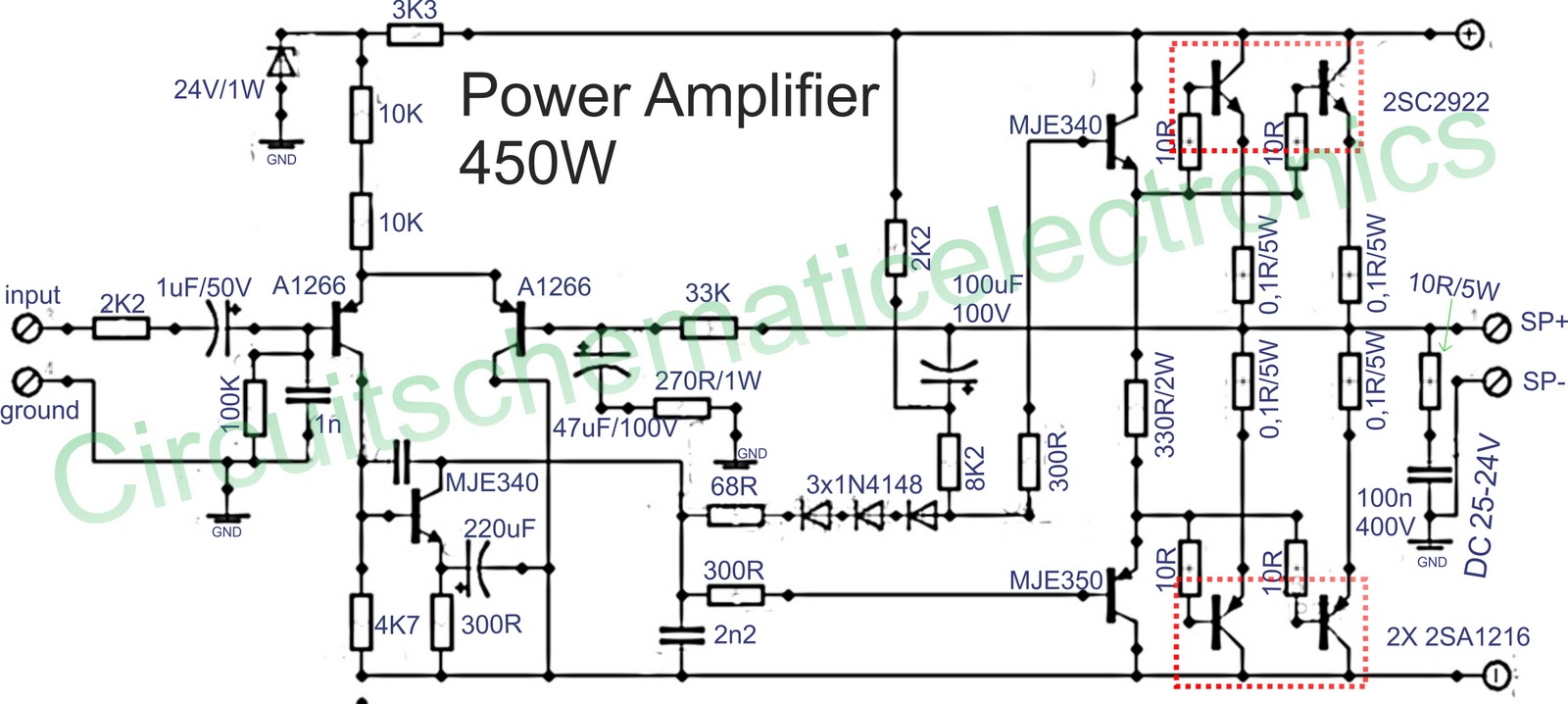
Below is a circuit of power amplifiers with a power output of 450 watts in mono mode. These amplifiers are frequently utilized in high-power applications, suitable for events, and designed for enclosed spaces. This amplifier is appropriate for woofers...
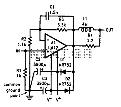
Output-clamp diodes are essential due to the inductive nature of loudspeakers. Output LR isolation is employed as audio amplifiers are typically designed to manage load capacitance of up to 2 µF. Large supply-bypass capacitors placed near the integrated circuit...
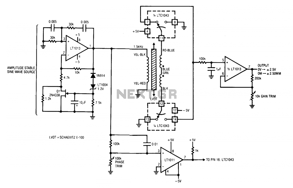
A1 and its associated components provide an amplitude-stable sine wave source. The positive feedback path utilizes a Wien bridge, tuned to 1.5 kHz. The LT1004 reference and additional components in A1's negative feedback loop stabilize the amplifier at unity...
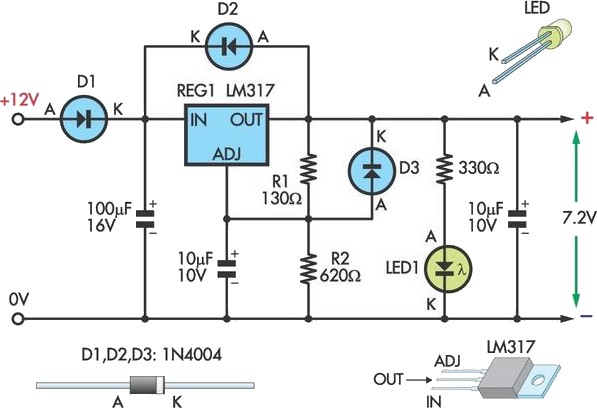
This circuit allows an external 12V SLA battery to power a camcorder that typically uses a built-in 7.2V battery. Obtaining such batteries for older camcorder models can be challenging and costly. The circuit utilizes a standard LM317 adjustable voltage...