flashing-light-uses-triacs.html

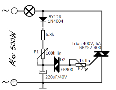
This flashing light circuit utilizes triacs to produce an intermittent light with a variable frequency. Additional components include a diode (D1) and a semi-adjustable potentiometer (R2). The trigger capacitor (C1) is increased from 0.1 µF to 220 µF to prepare the triacs for several successive cycles. The longer charging time of C1 results in the lamp flashing with a single pause lasting several cycles. The blinking frequency can be adjusted using potentiometer (P1). The semi-adjustable potentiometer (R2) regulates the gate current, influencing the lamp's lighting duration by determining the discharging time of C1.
This flashing light circuit is designed around the principles of phase control using triacs, which are semiconductor devices capable of controlling power. The primary function of the circuit is to create a visually dynamic lighting effect by varying the frequency of the light source. The inclusion of the diode (D1) serves to protect the circuit from reverse voltage, ensuring reliable operation and longevity.
The adjustment of the trigger capacitor (C1) from a lower value of 0.1 µF to a higher value of 220 µF is critical. This increase allows the circuit to sustain longer charging and discharging cycles, which in turn leads to a more pronounced flashing effect. The capacitor's role is to store electrical energy and release it at a controlled rate, thus influencing the timing of the flashes.
The potentiometers (P1 and R2) are essential for user interaction with the circuit. Potentiometer P1 allows for fine-tuning of the blinking frequency, enabling the user to customize the visual output to their preference. Meanwhile, R2 adjusts the gate current supplied to the triacs, affecting the overall brightness and duration of the light. This dual control mechanism provides flexibility in the operation of the circuit, making it suitable for various applications, from decorative lighting to signaling.
In summary, this flashing light circuit exemplifies the use of triacs for effective power control and offers adjustable parameters for tailored lighting effects. The combination of a larger capacitor and adjustable resistors facilitates a customizable and dynamic lighting experience.This flashing light circuit uses triacs to generate an intermittent light with patchy frequency. extra components are the D1 diode and semi modifiable potentiometer R2. The trigger capacitor C1 is increased from 0. 1 µF to 220 µF so to the triacs can be real prepared pro several successive periods. C1 ²s loading measure is longer, so to the lamp flashes with single pause of several periods. Blinking frequency can be adjusted with P1. Semi-adaptable potentiometer R2 regulates the current gate. This setting affects the lighting duration of the lamp since it moreover find out the C1 ²s discharging spell. You are reading the article about Flashing light uses triacs and you can find articles Flashing light uses triacs this the url.
You may distribute or copy articles Flashing light uses triacs this is beneficial if you or your friends, but do not forget to include the link source. 🔗 External reference