
FM Broadcasting
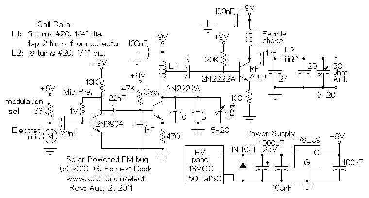
A metal enclosure is recommended instead of a plastic case, which is considered nearly useless. A box made from copper PCB was soldered together, which functions adequately but has room for improvement. It is crucial to ground the enclosure well and connect everything to a reliable earth ground. A well-filtered and regulated power supply is necessary; a 7812 regulator was installed on the underside of the board, along with additional filtering capacitance. The diode string for the BA1404 can be replaced with a regulator, ensuring not to exceed 3V. The balance control can be eliminated and replaced with a 50K resistor, which should be placed across the two pins on the chip, avoiding the + connection used with a potentiometer. Excessive wire length can introduce noise, instability, and feedback, so it is advisable to keep all components closely soldered to the board. A 70mW modification was implemented by tack soldering a 2N2222/2N4401 circuit on the underside of the board, achieving a 70mW output with a 1/4 wave vertical ground plane antenna. Although a solid watt can be achieved into a dummy load, only about 900mW is transmitted through coax, and approximately 750mW at the antenna. High-quality coaxial cable is recommended to minimize losses, as every bit of power is crucial when operating at low power levels. The power supply uses a small dual primary transformer that can be configured for 120/240V, with one primary for power input and the other rectified and filtered for B+. The transformer has two 10V, 600mA windings, currently regulated for filament power and bias. Plans to parallel these for a total of 1.2A for both filament and bias are in place. The coils were formed using a Sharpie pen with #16 solid wire, with the input coil consisting of four turns and the output coil five turns, plus one turn over it. For tuning, the bias should be adjusted to the lowest setting, the input peak adjusted for the highest reading on the input jack, and the output peak adjusted for the highest reading on the output, followed by a slight retouch of the input.
The circuit design emphasizes the importance of using a metal enclosure for enhanced shielding and grounding, which is essential for minimizing electromagnetic interference (EMI) and ensuring stable operation. The choice of copper PCB for the enclosure provides excellent conductivity and thermal management, promoting better heat dissipation compared to plastic cases.
For the power supply, the implementation of a 7812 voltage regulator ensures that the circuit receives a stable 12V output, which is critical for consistent performance. The addition of filtering capacitors aids in smoothing out voltage fluctuations, further enhancing the reliability of the power supply. The suggestion to replace the diode string with a regulator for the BA1404 is a prudent approach, as it can lead to improved voltage regulation and performance, provided the voltage does not exceed 3V.
The modification of removing the balance control and substituting it with a fixed resistor simplifies the design and reduces potential points of failure. The guidance to keep wiring short and components closely soldered to the board is crucial for maintaining signal integrity and reducing the risk of noise and feedback, which can severely impact audio quality.
The 70mW output achieved with the 2N2222/2N4401 circuit demonstrates a practical application of low-power transmission techniques. The selection of a 1/4 wave vertical ground plane antenna is appropriate for achieving a reasonable transmission range while maintaining compactness. The caution regarding coaxial cable quality and length is valid, as lower-quality cables can introduce significant losses, particularly in low-power applications.
The dual primary transformer design allows for flexibility in power input configurations, catering to different voltage standards. The regulated windings for filament and bias ensure that the circuit components receive the appropriate power levels, enhancing overall performance. The described coil construction method using a Sharpie pen as a form is a creative solution for achieving consistent coil dimensions, which is critical for optimal performance in RF applications.
Overall, the circuit design reflects a thorough understanding of electronic principles and practical considerations for achieving reliable and effective performance in a low-power transmission system.Metal enclosure, forget the plastic case they sell, it`s nearly useless. ( I made a box from copper PCB that I soldered together, it works okay, but could be better. ) Ground it to the enclosure well, and connect everything to a good earth ground. 4. Make sure you have a well filtered/regulated power supply. I put a 7812 regulator on the underside of the board. I also added more filtering capacitance for kicks. (Using free Sanyo Os-Con samples!)Also, you can replace the diode string for the BA1404 with a regulator, just don`t go over 3V! You can also ditch the balance control, replace it with a 50K resistor. If it isn`t exactly centered, it can screw with the stereo pilot, and stability. (put it across the two pins on the chip, don`t use the + connection, as you would on the potentiometer.
I havn`t actually tried this yet, but this is what the data sheet says. ) A note on changing/moving level controls, etc, Using excessive wire length for anything can result in noise, instability, feedback, etc! I advise that you keep all parts closely soldered to the board, and for example, don`t move the level controls to the front panel with any length of wire.
I did the well covered 70mw mod. Tack soldered a 2N2222/2N4401 circuit on the underside of the board. Got 70mw output. covered a fair area(half mile radius), with a 1/4wave vertical groundplane antenna hanging from my bedroom ceiling. Not bad! I can get a solid watt into a dummy load, but only 900mw or so into my coax (and even less *at* the antenna.
~750mw, and thats only about 10 feet of RG58!) Good coax is a wise investment, don`t skimp here! mini RG-8 is okay, there are others that are better. Try and keep cable runs short and connectors, etc. to a minimum to avoid extra losses. When transmitting with such low power, every little bit helps! ;-) For the power supply, I used a small dual primary transformer (configurable for 120/240V) and used one primary for power input, and the other was rectified and filtered for B+. (in the doubler circuit. )The transformer also has 2, 10V, 600ma windings I currently have both regulated, one for filament power, and the other for bias.
I plan to paralell them for 1. 2A, and drawing filament, and bias from a single point. For the coils, I used a Sharpie pen as a form (~12mm. dia), and used #16 solid wire. I believe the input coil was 4 turns, and the output was 5 turns, with 1 turn over it. (you`ll need to move the 1T coil side-to-side a bit for max power. Over the "cold" (B+) end of the coil seems best. ) To tune up: Adjust bias for lowest setting (fully negaitve) peak input for highest reading on input jack, peak output cap for highest reading on output, retouch input a bit, done!, Go broadcast some tunes, and sip a cold one. :-) 🔗 External reference
Related Circuits
Here are some utility circuits for use with the Ramsey FM10a, and other small FM stereo transmitter kits. This information may be helpful for setting up a micro powered FM radio station. The FM10a and similar kits tend to...
Here are some utility circuits for use with the Ramsey FM10a, and other small FM stereo transmitter kits. This information may be helpful for setting up a micro powered FM radio station. The FM10a and similar kits tend to...
Warning: include(partials/cookie-banner.php): Failed to open stream: Permission denied in /var/www/html/nextgr/view-circuit.php on line 713
Warning: include(): Failed opening 'partials/cookie-banner.php' for inclusion (include_path='.:/usr/share/php') in /var/www/html/nextgr/view-circuit.php on line 713