
FM TransmitterCircuit & Project Kits

The transmitter circuit operates on a Printed Circuit Board (PCB), which is designed for compactness and efficiency. The use of track inductors for L1, L2, and part of L3 allows for a streamlined layout that minimizes space while maintaining performance. The oscillator section, centered around transistor Q1, is critical for generating the desired frequency. The tank circuit formed by L1, C4, and C5 is essential for establishing stable oscillations. The feedback provided by capacitor C5 is crucial for maintaining oscillation, directly impacting the stability and frequency of the output signal.
Modulation is introduced at the base of Q1 via coupling capacitor C2, enabling the integration of audio signals into the RF transmission. The inclusion of a microphone allows for real-time audio input, while the option to connect direct audio signals enhances flexibility for various applications. The biasing resistor R1 can be disconnected to facilitate this alternative audio input, ensuring that the circuit remains versatile.
Transistors Q2, Q3, and Q4 are configured in a manner that allows for gradual amplification of the RF signal, ensuring that the output reaches the required power levels without distortion. The RF output is taken from the junction of capacitors C11 and C12, which serve to filter and stabilize the output signal. The unbalanced output impedance of approximately 75 ohms is typical for RF transmitters, but it necessitates the use of a BALUN to connect to a balanced antenna system.
The 1:4 BALUN is specifically designed to match the impedance of the folded dipole antenna, which operates at around 300 ohms. This matching is vital for efficient power transfer and to minimize reflections that could lead to signal loss. The choice of a 300-ohm flat parallel feeder cable for the antenna connection is advantageous, as it reduces costs compared to coaxial cables while also providing lower signal loss, which is beneficial for maintaining signal integrity over distances. This design choice reflects a practical approach to RF transmission, balancing performance with cost-effectiveness.The transmitter is built on a Printed Circuit Board. This board uses track inductor for L1, L2 and part of L3. The section built around Q1 is the oscillator section. Oscillation frequency is determined by L1, C4 & C5 which forms the tank. Actually C5 is the feedback capacitor. This is required to sustain oscillation. This also influence the operat ion of tank formed by L1 & C4. Modulation is directly applied to the base of Q1 via C2. A microphone is connected here to serve this purpose. You can alternately feed direct audio here after disconnecting the microphone biasing resistor R1. Q2, Q3 & Q4 gradually raises the output power up to the desired level. RF output from the transmitter is taken from the junction of C11 & C12. This is unbalanced output of around 75 ohms impedance. But a folded dipole is a balanced type antenna of around 300 ohms impedance. So we need to use a `BALanced to UNbalanced transformer` or `BALUN`. A 1:4 type BALUN is employed here for this purpose. Antenna connection is taken from this BALUN via a 300 ohms flat parallel feeder cable commonly used in television to receive terrestrial broadcast. No coaxia is used to feed antenna. This saves cost. Also a parallel feeder cable provides much less signal loss compared to a coaxial. 🔗 External reference
Related Circuits

Best Microcontroller Projects. Do you want to learn how to use a microcontroller in your electronic projects, or do you need inspiration for your next project? If so, you have found the right place! Here is a tutorial on...

The 12F629/675 PICs are compact 8-pin DIP devices suitable for various applications. They feature an internal oscillator, a comparator, an analog-to-digital converter, and timers. The Microchip PICkit1 serves as an effective USB programmer. PicBasic Pro (PBP) is a user-friendly...
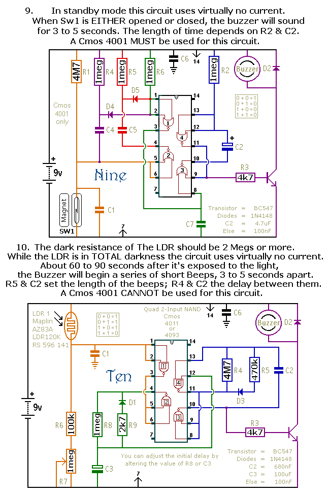
This document outlines a selection of small self-contained alarm circuits. Each alarm's main features are detailed on the circuit diagram. They are designed to have a very low standby current, making them suitable for battery operation. Each pair of...
The AVR Basic Infrared Transmitter is a companion project to the Basic Infrared Receiver. This project is termed "basic" because it can be constructed using only 10 discrete components along with a standard AVR microcontroller. Together, these two projects...
This website does not collect any personal information unless contacted via email. If an email is sent, the name, email address, and any other personal information provided will be used solely to respond to the message. Personal information will...

This wideband amplifier circuit is designed using the MAR-6 IC manufactured by Mini Circuits. The MAR-6 VHF-UHF wideband amplifier circuit provides a stable gain of at least 9 dB up to 2 GHz. Since the MAR-6 is designed to...