
FM VFO circuit

The described circuit utilizes an inductor constructed from 8 turns of #24 insulated solid copper wire, wound around a 5 mm screwdriver for form. This choice of wire and method of construction allows for effective handling and manipulation during assembly. The use of a conductor from a category 5 quad twisted pair enhances the ease of stripping insulation, which is crucial for maintaining the integrity of the wire during the assembly process.
Tuning the circuit is facilitated by a 10-turn panel-mounted potentiometer, which allows for precise adjustments across the FM band. The upper modulation frequency is constrained by a 39 kΩ input resistor in conjunction with a shunt capacitance, estimated to be around 20 pF. This configuration is designed to ensure stable operation up to several MHz, making it suitable for various RF applications.
The construction methodology recommended is a ground plane board layout, which is essential for minimizing noise and interference. The "dead bug" technique is employed for rapid assembly, where components are soldered directly onto a copper-clad board, with grounded parts connected to the copper cladding and ungrounded parts connected to the leads of grounded components. This approach is particularly effective for high-frequency circuits, as it reduces lead length and associated parasitic effects.
Shielding is a critical aspect of the design, implemented to protect the circuit from interference from nearby RF sources. A five-sided copper box is constructed and soldered to the ground plane, providing a robust means of shielding. The use of a 330 Ω build-out resistor on the emitter follower contributes to the isolation of the oscillator from its load, enhancing circuit stability.
Overall, careful attention to layout, component placement, and shielding techniques is paramount to the successful operation of this high-frequency circuit, ensuring minimal interference and optimal performance.The inductor is made by winding 8 turns of #24 insulated solid copper wire on a 5 mm screwdriver. I used a conductor from a piece of category 5 quad twisted pair, left over from wiring the house with Ethernet and this seems to work well and to be easy to handle. Stripping the vinyl insulation is much easier than scarping or burning off enamel. This was easily tuned up and down the bottom of the FM band using a 10 turn panel mounted potentiometer.
The upper limit to the frequency modulation is set by the 39 k input resistor and the shunt capacitance (I would guess around 20 pf max), so that shouldn't be a concern until the modulation frequency reaches many MHz. Build this on a ground plane board. Layout is important. If you place the parts relative to one-another in correspondence with their placement on the schematic, it should work pretty well. For making one or two of something, I don't like to bother with a printed circuit boards. I just cut off a 2.5 x4 cm piece of copper clad board and soldered grounded parts onto the copper cladding fiberglass, and the ungrounded parts directly onto the leads of the grounded parts.
This "dead bug" construction is a very speedy way to put high frequency circuits together and it works pretty well at these frequencies. One thing to be careful of is to make sure all the components are packed tightly so as to minimize parasitic resulting from long leads.
In the ones I built, the components are leaded, though in one of them I used chip capacitors for the bypass capacitors, though I couldn't see any difference in performance. It was necessary to shield the circuit so that it would not be affected by other circuits nearby, particularly additional RF stages.
The loose coupling for the RF, provided by the 330 build-out resistor on the emitter follower further serves to isolate the oscillator from its load. These result in greater stability. The shield was made by forming a five-sided box (one side missing) from tooling copper (a thin copper sheet) and soldering it onto the groundplane of the copper clad board.
Once, for something similar, I made a shield box by soldering pieces of copper clad board together. Nearly anything will do as long as its reasonably low resistance material (brass shim stock should work if you have a piece laying around). 🔗 External reference
Related Circuits
This document provides a guide on understanding a simple computer system and its operation. It will examine the BASIC programming language and its statements, enabling communication with external circuitry. The document will also explore how to interface electronic circuits...

This circuit is similar to the one found in the Single Buss 1V/Octave Keyboard Controller. Refer to the circuit description there for more details. This board includes additional resistors used in the keyboard voltage divider. In a typical keyboard,...
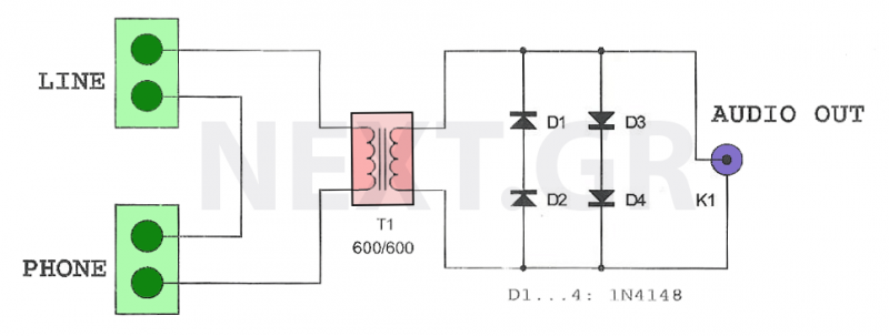
This circuit is designed to record telephone conversations on a landline telephone. It requires a small circuit and a computer subscription. Recording conversations is useful for recalling important discussions. Previously, this was accomplished using a small tape recorder, where...
The thermistor utilized has a resistance of 15k ohms at 25 degrees Celsius and 45k ohms at 0 degrees Celsius. A suitable bead-type thermistor can be sourced from the Maplin catalogue. The inclusion of a 100k potentiometer enables this...
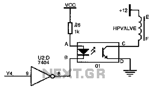
The driver circuit for the high-pressure natural gas shut-off valve utilizes solid-state relays. In dual-fuel mode operation, the fuel switching mechanism is controlled by a logic section that activates Y4 to a high state via U2 (7404 inverters). This...
This circuit deactivates an amplifier or any connected device when a low-level audio signal is absent at its input for at least 15 minutes. Activating switch P1 powers the device, enabling operation of any appliance connected to SK1. The...