
Four quadrant photo-conductive detector amplifier

The circuit operates by utilizing photodetectors aligned along the X and Y axes to capture the intensity of light. Each photodetector generates a voltage proportional to the light intensity it detects. The NE/SE5514 integrated circuit is essential for processing these signals, as it features differential inputs that allow for precise summation of the X and Y signals.
In a typical configuration, two photodiodes are positioned to face the light source, one aligned horizontally (X-axis) and the other vertically (Y-axis). The output voltages from these photodiodes are fed into the NE/SE5514, which performs the necessary signal conditioning and amplification. The output from the IC reflects the position of the light source in a four-quadrant coordinate system, enabling accurate tracking of its motion.
The summed output can be connected to an X-Y plotter, which graphically represents the light source's movement across a two-dimensional plane. Alternatively, the output can be directed to an oscilloscope to visualize the changes in voltage over time, or to a computer for further analysis and simulation. This versatility makes the circuit suitable for various applications, including robotic vision systems, light tracking mechanisms, and experimental setups in optics research.
In summary, this circuit provides a compact and efficient solution for sensing and visualizing the motion of a light source in a four-quadrant space, leveraging the capabilities of the NE/SE5514 integrated circuit for optimal performance.Use this circuit to sense four quadrant motion of a light source By proper summing of the signals from the X and Y axes, four quadrant output may be fed to an X-Y plotter, oscilloscope, or computer for simulation. IC = NE/SE5514.
Related Circuits
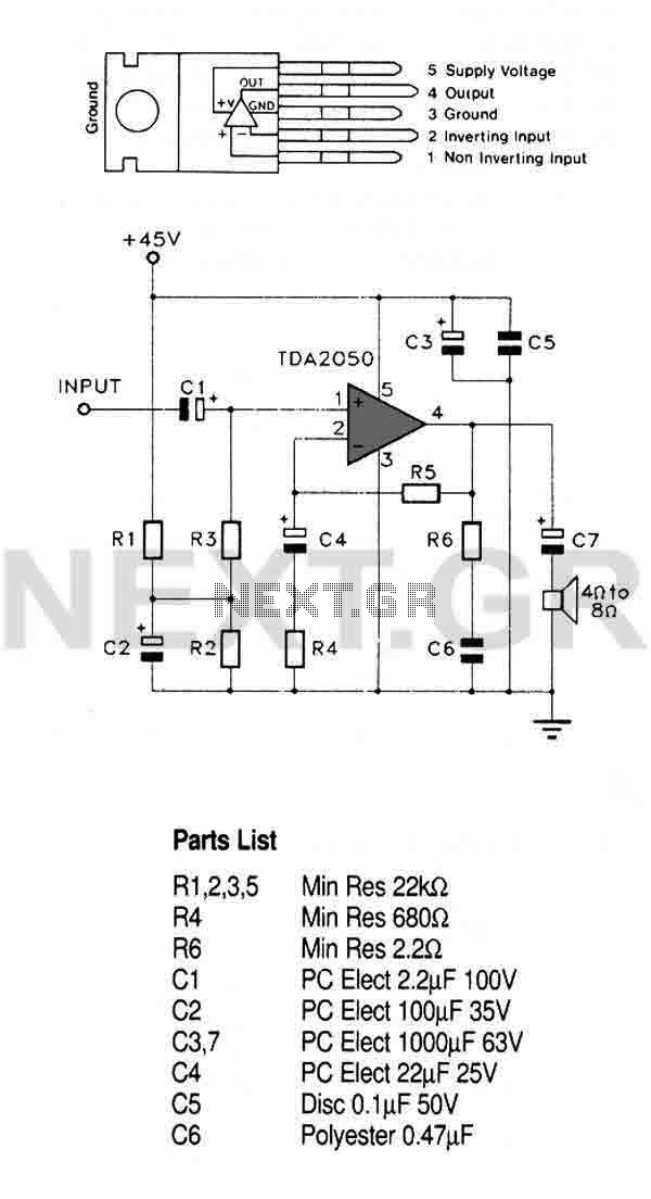
This circuit utilizes a high-quality audio amplifier integrated circuit (IC) housed in a 5-pin TO220 package, which eliminates the need for insulating washers between the metal tab and heatsink in single rail supply applications. The amplifier is capable of...
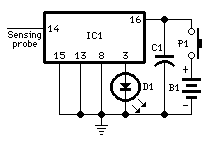
Detects the presence of a live mains conductor. Minimum parts counting. If the unit is brought close to a live conductor (insulated, and even buried in plaster) capacitive coupling between the live conductor and the probe clocks the counter,...
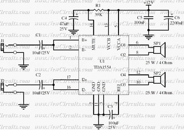
Very simple and useful circuit for amplify the stereo signals. The circuit dissipates roughly 28 watts of heat, so a good heatsink is necessary. The chip should run cool enough to touch with the proper heatsink installed. The circuit...
The JBL "Bass Wave" amplifier is a compact 100-watt amplifier featuring a built-in active filter that includes a single-pole high-pass filter at 10 Hz and a single-pole low-pass filter at 85 Hz. Priced at an affordable $50 USD, it...
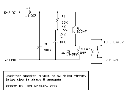
This is a simple circuit designed for an audio amplifier project to control the speaker output relay. The purpose of this circuit is to manage the delay that activates the relay, which connects the speakers to the audio amplifier....
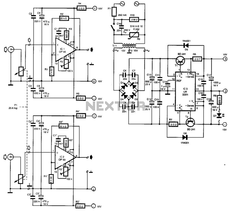
Built around Precision Monolithics Inc. OP-50 operational amplifiers, this amplifier is capable of driving 100- to 14-ohm headphones. It maintains a flat frequency response within 0.4 dB from 10 Hz to 20 kHz and exhibits a total harmonic distortion...