
FPGA / CPLD 16x2 LCD Interface Circuit

The schematic integrates several critical components to facilitate the operation of the CPLD-based system. The CPLD development board serves as the core processing unit, enabling complex logic operations and interfacing with peripheral devices. The 16x2 LCD (HD44780) is a widely used display module that provides a user interface for outputting information. In the 8-bit configuration, it connects to the CPLD via 11 digital I/O lines, which include data, control, and enable signals, ensuring efficient communication between the CPLD and the display.
The ByteBlasterMV is employed as a programming interface, allowing for the configuration of the CPLD through JTAG. This connection is vital for downloading the programmed logic into the CPLD, enabling it to execute the desired functions as defined in the design.
Power supply considerations are essential, with the LCD requiring a stable voltage and current for proper operation. The inclusion of a 5kΩ trimpot for contrast adjustment allows for fine-tuning the display visibility based on ambient lighting conditions.
The oscillator is a crucial component, providing the necessary clock signal for the CPLD to synchronize its operations. The choice of an oscillator with a frequency above 10 MHz ensures that the system operates efficiently, meeting timing requirements for the various logic functions implemented within the CPLD.
Overall, this schematic represents a well-thought-out integration of components that work together to create a functional CPLD-based project, allowing for both programming flexibility and user interaction through the LCD display.The schematic for this project is a modified version of the CPLD dev board schematic. There are a few new parts added for this project and you can see the completed schematic for this project below. The main parts in the schematic are the CPLD Dev Board, 16x2 LCD (HD44780) and ByteBlasterMV. The 16x2 LCD makes 11 digital I/O connections to the CPLD/FPGA when used in 8-bit mode (In 4-bit mode, only 7 connections are necessary). Since we`re using 8-bit mode all of these connections are necessary. The rest of the LCD`s pins are power connection and contrast from the 5k © trimpot. This protoboard for a cpld was developed by me a few years ago. It`s really just a PLCC CPLD in a socket with power and JTAG connectors for programming. This oscillator was chosen mostly at random. We needed some type of timing device to keep a reference to time and I had this one laying around. Generally if you can find a clock above 10 MHz you`ll be fine for this project. 🔗 External reference
Related Circuits
Most universal radio receivers have a very wide bandwidth that is not particularly suitable for radio amateurs. The better models with narrower bandwidth are almost a... Universal radio receivers are designed to operate over a broad frequency range, making them...
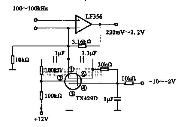
A variable gain amplifier is presented. This circuit adjusts the output signal amplitude based on the input signal. The core component is an operational amplifier configured with a negative feedback circuit. By varying the feedback amount, the gain of...
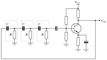
An FM transmitter circuit that utilizes a low power configuration, employing an operational amplifier as an audio preamplifier and a single transistor to function as the RF amplifier. This FM transmitter circuit is designed for low power applications, making...
For successful circuit-building exercises, follow these steps: Measure and record all component values before constructing the circuit, selecting resistor values that are sufficiently high to minimize the risk of damaging any active components. In case of significant errors (greater...
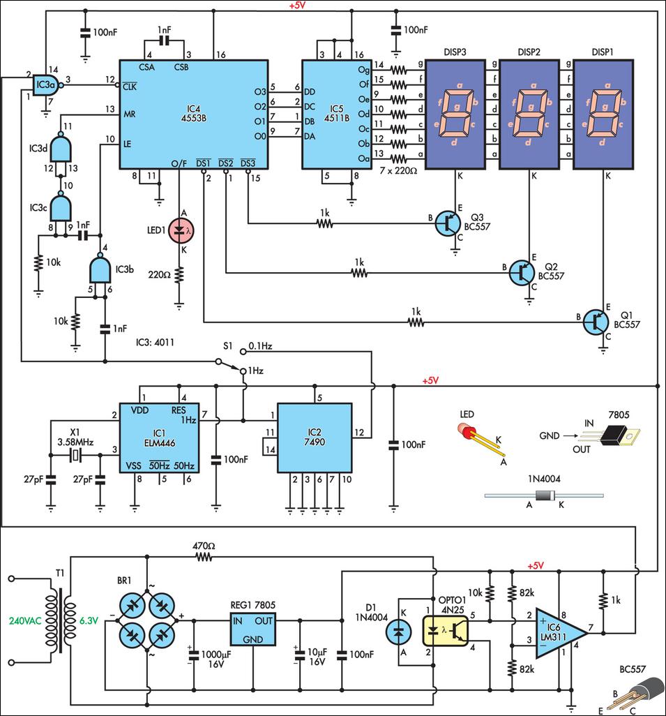
This is a simple frequency counter designed to monitor the 240VAC mains supply. It has a frequency range of 0-999Hz, making it suitable for use with 400Hz equipment as well. Standard TTL/CMOS logic is utilized for the counters and...
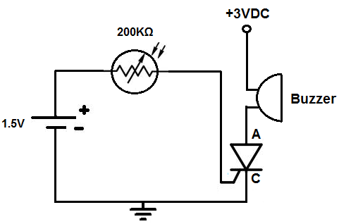
This circuit activates an alarm when it detects a specific level of light. When the light exposure increases beyond a predetermined threshold, a loud buzzer sounds, providing an alert. The alarm remains inactive in low-light conditions but triggers in...