
Free-Electron Pump (FEP) Experiments
 Experiments")
I built an oscillator using a 555 IC to drive an auto ignition coil with a BUZ30A-type SIPMOS transistor. Tests conducted with this circuit yielded results indicating that placing aluminum foil on the fluorescent lamp maintained a consistent DC power supply, except when a very large aluminum foil was taped to the wall. The supplied DC power was also influenced by the oscillator's frequency and duty cycle, with higher frequencies resulting in lower DC power consumption. The system can be fine-tuned to achieve maximum brightness with minimal power supply. As the size of the aluminum foil increases, the brightness of the fluorescent lamp correspondingly increases. In cases involving very large foil taped to a wall, a reduction of at least 3.5 W in DC power was observed, along with a significant increase in brightness.
An experiment was conducted where a medium-sized foil was immersed in a plastic container filled halfway with tap water. The brightness of the fluorescent lamp remained consistent with the medium foil alone, and the circuit consumed similar DC power. However, when the foil was removed and the high-voltage lead was placed directly in the water, no changes were observed. Notably, drawing a spark from the aluminum foil revealed a pink-purple arc rather than a blue spark, with increased intensity at the sharp edges of the foil, indicating high current density. This arc is attributed to the additional electrons being drawn by the system.
Multiple fluorescent lamps can be activated using an input power of several watts from a 12V battery, which can be recharged via a solar panel. This setup significantly reduces lighting costs and serves as an excellent primary or backup lighting solution for homes, factories, campers, travelers, and boat owners. The lamps can be connected in parallel, with one end of each lamp capacitively linked to the high-voltage terminal and the other end connected to aluminum foil.
The inverter circuit's design allows for efficient operation and adaptability, making it suitable for various applications, especially in off-grid or renewable energy scenarios. The use of aluminum foil not only enhances the performance of the fluorescent lamp but also illustrates the principles of electric fields and ionization in enhancing conductivity and light output.A simple two-transistor inverter circuit has been built for this experiment. The transformer shown in Fig. 1 is the inverter transformer. The inverter output voltage is in the form of pulses with an estimated peak value of about 700V. When a Fluorescent lamp is connected as shown in Fig. 1(a), the lamp is quite dim. When I place an aluminum foil on top of the lamp, it lits brighter (though not as bright as when it’s connected to the transformer’s secondary). How this happens?
The high voltage terminal which is connected to the Fluorescent lamp ionizes the gas inside the tube. As more electrons are released from the gas molecules (or atoms), it becomes more conductive. This in turn shorts the HV connected terminal of the FL lamp to the open terminal with minimal resistance.
And the open terminal now has the same high potential. When I attach a large aluminum foil, it too is charged to this potential due to conductive path formed by the ionized gas. And the high potential causes more free electrons to be sucked from the aluminum foil by the transformer secondary which acts like a sink.
Therefore, additional electrons from the gas medium, and the aluminum foil are supplied, and in turn the lamp gets brighter. Larger metallic sheets will supply even more electrons. The secondary HV terminal acts as a sink, which generates the + potential and sucks the electrons. The moving electrons due to high potential are released by the – terminal of the secondary.
2 FEP Experiments
I built an oscillator based on 555 IC and drove an auto ignition coil using a BUZ30A-type SIPMOS transistor.
The circuit can be seen in Fig. 3. I conducted some tests using the above circuit. Results are summarized in Tables 1 and 2.
Both tests indicate that by placing an aluminum foil on the Fluorescent lamp, the supplied DC power was about the same, except for the case of a very large aluminum foil taped to the wall. The supplied DC power is also dependent on oscillator frequency and duty cycle. Higher frequencies yield lower DC power consumption. It’s possible to fine tune the system so that for a minimum supply power, maximum brightness can be obtained.
As the size of the foil increases, the brightness of the Fluorescent lamp increases, which is shown in Fig. 4. For the case of very large foil taped to wall, the DC power dropped by at least 3.5 W for both tests, and the brightness increased significantly.
I immersed the medium foil in a plastic container that is half-full with tap water, and observed that FL lamp has about the same brightness when the medium foil is used alone. And the circuit consumed about the the same DC power. Then, I removed the foil and put the HV lead directly into the water. Nothing was changed. When I draw a spark from the aluminum foil, I notice that the spark is no longer blue. But it has a pink-purple color reminding an arc. And at sharp edges of the foil, the intensity of the arc was more. An arc indicates a high current density. Additional electrons sucked by the system must be the reason for this arc.
Several Fluorescent lamps can be turned ON using an input power of several watts supplied by a 12V battery.
The battery can be recharged from a solar panel. Such an equipment will lower the cost of lighting a lot, and it’s especially great as main or backup light for homes, factories, campers, travelers, and boat owners. Lamps can be connected in parallel. One end of a lamp is capacitively connected to the HV terminal and the other end is connected to aluminum foil.
Related Circuits
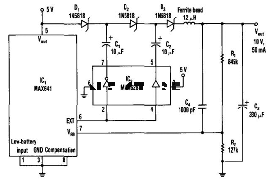
The DC-DC converter replaces a voltage tripler for the external inductor and diode typically associated with the switching regulator, IC1. Inverting and non-inverting amplifiers in the MOSFET driver (IC2) activate a diode-capacitor tripling network (D1 through D3, C1 through...

The initial design utilized a small flyback transformer from an old computer, paired with a simple driver circuit based on a 555 integrated circuit (IC). This circuit featured AC coupling to the driver transistor and was assembled on a...

SM indicates that the tube can produce certain frequencies and discusses the use of TV tubes to achieve improved sound quality at higher frequencies. The effectiveness of this approach can only be determined through experimentation with the specified frequency...

MP3 players have gained immense popularity, especially the compact memory-stick format, which allows for easy portability and personal music enjoyment on the go. However, when sharing music with others, these players often lack sufficient power. A solution to this...
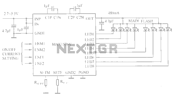
The circuit utilizes the MAX1576Y charge pump white LED driver, capable of supplying a total current of up to 480mA across two groups (n = 4 white LEDs). Each white LED in the flashing group can draw a maximum...
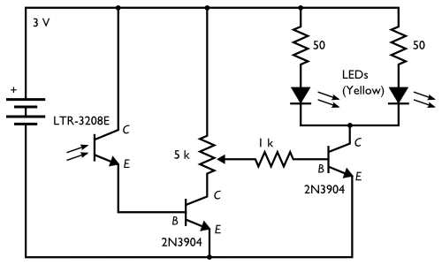
The concept involves placing a pair of yellow LEDs inside a pumpkin, combined with a photo sensor that activates the lights at night. The circuit is simple, utilizing minimal components. Two schematics are provided on the project site, with...