
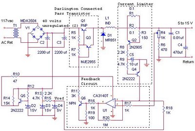
Free Energy Schematic

The circuit design for this concept typically includes several key components. The high-frequency source can be generated using an oscillator circuit, which may utilize a crystal oscillator or a high-speed transistor-based oscillator to achieve the desired frequency. The output of this oscillator is directed to a rectifier circuit, which can be constructed using diodes capable of handling high voltage and fast switching speeds, such as Schottky diodes. This rectification process converts the alternating current (AC) signal into direct current (DC), allowing for efficient charging of the capacitors.
The bank of capacitors is selected based on the required capacitance and voltage ratings, ensuring they can handle the high-voltage charge without risk of breakdown. Capacitors such as tantalum or ceramic types may be suitable due to their ability to maintain stability under high-frequency conditions.
For the discharge phase, a high-speed electronic switching circuit is critical. This can be achieved using MOSFETs or IGBTs (Insulated Gate Bipolar Transistors), which are capable of switching on and off at very high speeds, allowing for precise control over the discharge timing. The discharge circuit is designed to release the stored energy from the capacitors in short, controlled pulses, which can be utilized for various applications, such as in pulsed power systems or high-energy physics experiments.
To ensure that the high-voltage charge flows in one direction only, a unidirectional rectification method is employed. This can be achieved through the use of a bridge rectifier configuration or by implementing a combination of diodes in series with the capacitors.
Overall, this circuit design encapsulates a sophisticated approach to managing high-frequency, high-voltage signals for energy storage and rapid discharge applications, emphasizing the importance of component selection and circuit configuration to achieve optimal performance.The basic concept as I understand it, is a high frequency high voltage low current rectified and then used to charge a bank of high value capacitors and then to discharge them in pulse mode for brief period of time, nano seconds in fact by, means of a high speed electronic switching circuit or mechanical device and a rectification method that will only allow the high voltage charge to flow in one direction. 🔗 External reference
Related Circuits
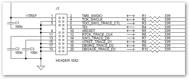
This interface schematic illustrates the JTAG, Serial Wire, and ETM interface circuits of ULINKpro. It can be utilized to analyze potential issues with the target hardware. The schematic represents the interconnections and functionalities of the JTAG (Joint Test Action...
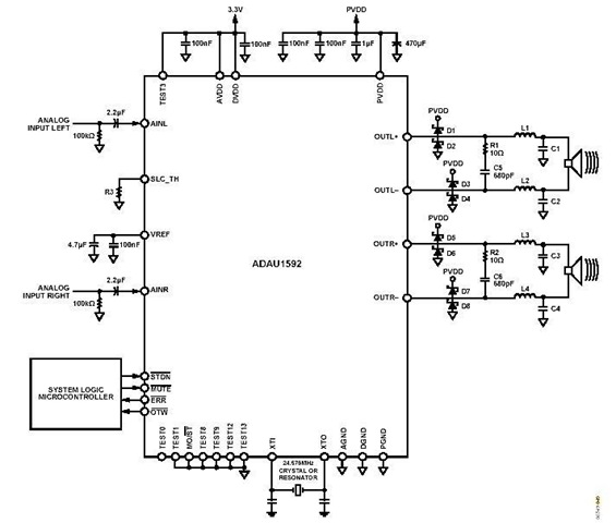
This is a stereo circuit schematic of the ADAU1592, a 2-channel, bridge-tied load (BTL) switching audio power amplifier. The ADAU1592 can be utilized in compact television sets, PC audio systems, and mini-component applications. According to the ADAU1592 datasheet, an...
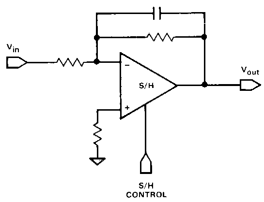
Circuit 1kZ incorporates an operational amplifier (op-amp) component with two inputs, one output, and up and down ports, typically utilized for power supply rails. Additionally, there is a buffer component, which is likely provided by TikZ itself rather than...
The schematic consists of three main components. The first component is the sensor circuitry, which connects the accelerometer to the analog-to-digital converters (A/D converters). The second component is the power circuit, featuring an On/Off switch, a 3.7V battery, and...
The described shunt-feedback configuration facilitates the straightforward incorporation of frequency-dependent networks, enabling a practical and unobtrusive switchable tilt control as an optional feature. When switch SW1 is in the first position, a gentle shelving bass boost and treble cut...
The switching power supply provides 12 volts at a maximum of 10 amps, utilizing a discrete transistor regulator with an operational amplifier acting as a comparator in the feedback circuit. The schematic does not depict the front panel power-on...