
Frequency-counter

The described circuit utilizes a 555 timer configured in astable mode to generate a frequency output that correlates with an input voltage. The astable multivibrator operates continuously, producing a square wave output at pin 3. The frequency of this output is primarily influenced by the resistors R2, R3, and R4, as well as the voltage applied to pin 6.
In this configuration, R2 plays a critical role in determining the base frequency of the output when the input voltage is at its minimum (0 V). The resistance values of R3 and R4 are crucial for scaling the output frequency in response to variations in the input voltage. Specifically, R4 is designed to ensure that each 1 V increment in the input voltage results in a 10 Hz increment in the output frequency. This relationship is established when the combined resistance of R3 and R4 equals 1.2 MΩ.
Calibration of the circuit is essential for accurate frequency output. Initially, the voltage probes should be shorted, allowing for the adjustment of R2 until the frequency counter indicates a reading of 0 Hz. This step ensures that the circuit is correctly set to register no output frequency at the lowest input voltage. Subsequently, a precise 5 V source is measured using the voltage probes, and R4 is adjusted to achieve a frequency counter reading of 50 Hz. This calibration process aligns the output frequency with the expected changes in input voltage, ensuring reliable performance across the specified range.
Overall, this circuit design is effective for applications requiring voltage-to-frequency conversion, allowing for easy measurement and monitoring of varying voltage levels through frequency changes.The output frequency from IC pin 3 is determined by the voltage input to pin 6. A standard frequency counter can be used to measure voltages directly over a limited range from 0 to 5 V. In this circuit, the 555 is wired as an astable multivibrator. Resistor R2 oetermines the output frequency when the input to the circuit (the voltage measured by the voltage probes) is zero.
R4 is a scaling resistor that adjusts the output frequency so that a change in the input voltage of 1 V will result in a change in the output frequency of 10 Hz. That will happen when the combined resistance of R3 and R4 is 1.2 MO. To calibrate short the voltage probes together, adjust R2 until the reading on the frequency counter changes to 00 Hz. Then, use the voltage probes to measure an accurate 5-V source and adjust R4 until the frequency counter reads 50 Hz.
Related Circuits

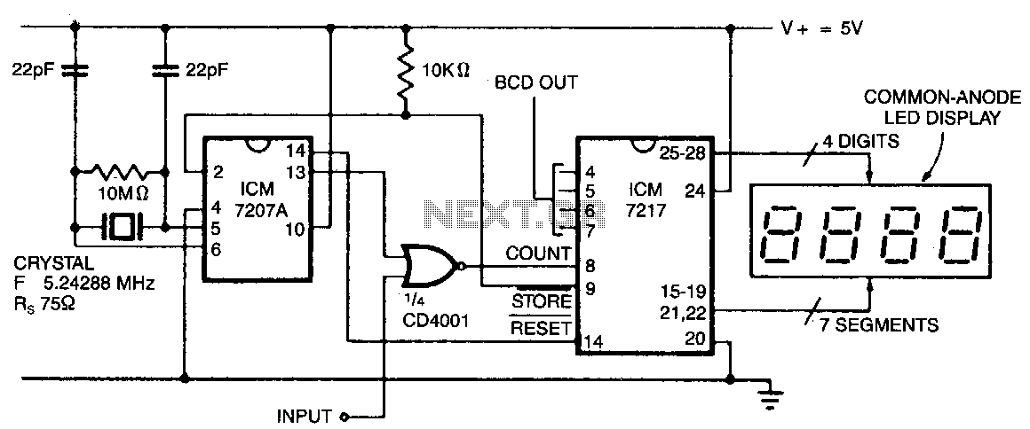
This counter utilizes a four-digit display, which can show frequencies ranging from 1 to 40 MHz when the range switch is activated, achieving a resolution of 100 Hz. The MM74C926 CMOS integrated circuit features a four-digit decimal counter that...
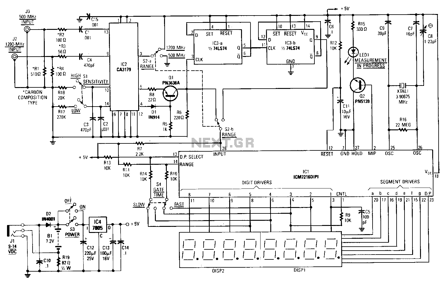
The output of the CA3179 is fed through the D1Q1 circuit. These components serve to boost the 1V output of the CA3179 to a standard TTL level. Depending on the position of range switch S2b, the signal is passed...
In this configuration, the display shows hertz directly. When pin 11 of the ICM7027 A is connected to V00, the gating time is set to 0.1 seconds, allowing the display to represent tens of hertz as the least significant...
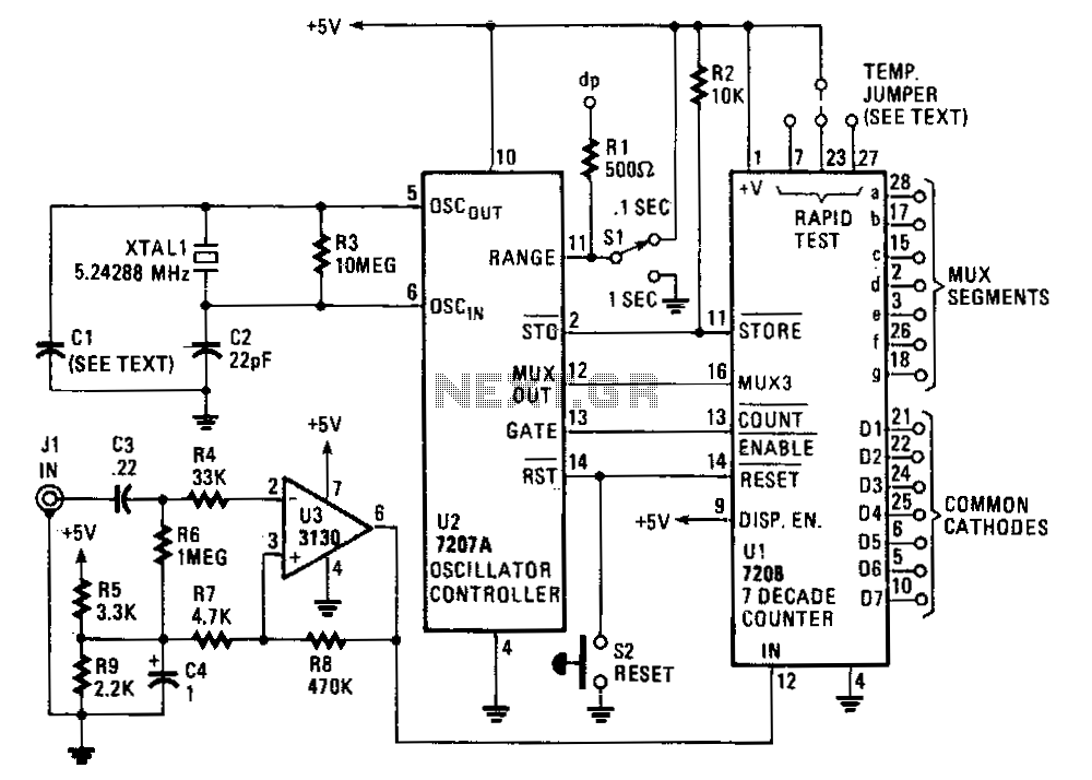
The circuit comprises an ICM7208 seven-decade counter (U1), an ICM7207A oscillator controller (U2), and a CA3130 biFET operational amplifier (U3). The ICM7208 (U1) counts input signals, decodes them into a 7-segment format, and outputs signals to drive a 7-digit...
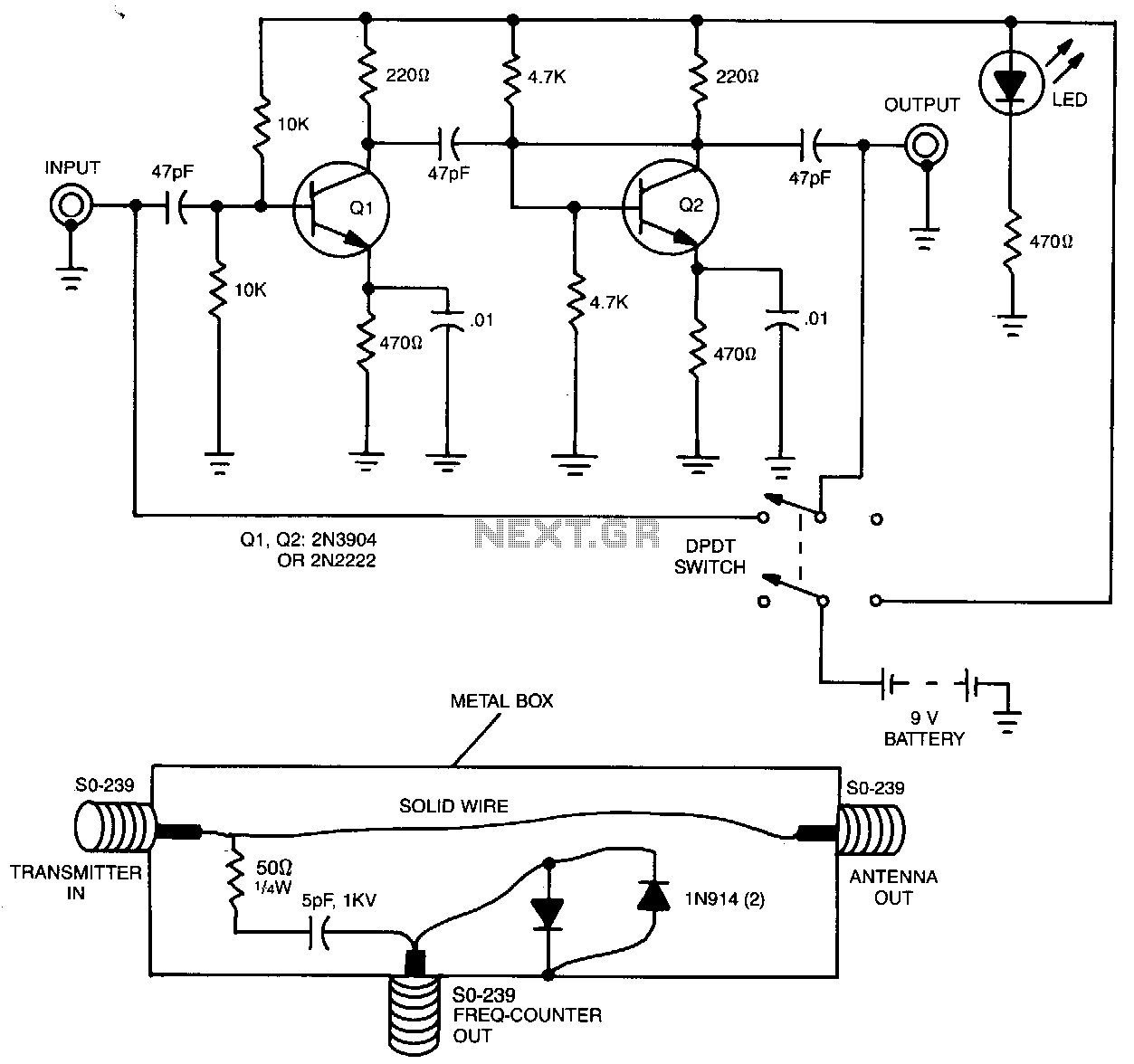
The preamplifier, when utilized with a short length of shielded cable and clip leads, allows signals that typically do not produce a readout to generate precise and stable readings on the counter. A DPDT switch is incorporated to bypass...
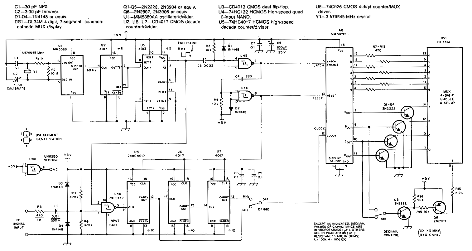
This counter features a four-digit display that can be switched to display frequencies ranging from 1 to 40 MHz, with a resolution of 100 Hz. The MM74C926 CMOS IC serves as the four-digit decimal counter, which can latch a...