
Frequency counter

The frequency counter circuit is built around the Atmel ATTiny2313 microcontroller, which serves as the core processing unit. The microcontroller is responsible for handling the counting of frequency signals and managing the display output. The circuit's design includes a power supply section that ensures stable operation, typically supplied by a regulated voltage source.
The display section employs two 3-digit common anode 7-segment displays, which are connected to the microcontroller's PORTD for digit control and PORTB for segment control. Each segment of the display is driven by a corresponding pin from the microcontroller, allowing for the representation of numerical values. The use of 220-ohm resistors in series with each segment helps to limit current and protect the LEDs within the display.
The frequency input is connected to the Timer/Counter1 input pin (PD5), where it measures square wave signals. To accommodate varying input signals, a Schmitt trigger (such as the 74HC132) can be used to ensure that the input signal is clean and well-defined, improving measurement accuracy. The circuit can accommodate a range of frequencies up to 2 MHz, with the potential to extend this limit to 4 MHz by using an 8 MHz quartz crystal, following appropriate adjustments to the software routines.
The timing and counting mechanism relies on Timer/Counter0, which is configured to generate interrupts at regular intervals (every 2 ms) to facilitate the gate timing for frequency measurement. The software counter increments with each interrupt until it reaches a predetermined value, at which point it stops counting and updates the display with the measured frequency.
The overall layout of the circuit on the perf board is designed for compactness, with vertical wiring for components to minimize space usage. This design approach ensures that the frequency counter can be easily integrated into a larger system, such as a frequency generator box, while maintaining functionality and readability of the display. The use of a translation table in software allows for flexibility in accommodating different display types, ensuring that the counter can be adapted as necessary for various applications.This Frequency Counter is suitable to display the frequency of a frequency generator with an analog setting. It is a very simple counter and can be used as a module in a box with a frequency generator. It does what it says, it measures frequencies up to 2 MHz and shows the frequency on a 6 digit 7 segment display.
The resolution is 10 Hz, we have only 6 digits because I once got a bag full of 3 digit common anode displays and here we already use all available pins on an Atmel ATTiny2313. Here you see it in a box with two frequency generators and it shows the frequency in kHz. In the box, on the left is a 15Hz to 30 kHz dds sine wave generator and on the right is one with the famous XR2206, the switch below the display switches between the right and left side frequency display.
Here it shows the maximum frequency of the XR2206. Components needed for this small project are one Atmel ATTiny2313, eight 220 Ohm resistors, two 3 digit common anode displays and one 4 MHz quartz, which I just had in the box. It`s possible to use e. g. a 8 MHz quartz which would extend the frequency to 4 MHz but then the the gate routines need adjustment, easy to do.
It is programmed in assembly language and compiled with gavrasm. Timer/Counter1 is used as the frequency counter and Timer/Counter0 for the gate time. At Timer/Counter1 count input T1 PD5 (Pin 9) the frequency is measured. A square wave should be present at this input so it could be wired to a Schmitt trigger front end as e. g. a 74HC132 to shape sinewaves. With a prescaler of 64 and a compare value of 125 a Timer/Counter0 Compare Match A interrupt fires every 2 ms.
This interrupt is used for for gate timing and to update the display. One software counter counts to 50, then stops Timer/Counter1 and displays the result. The gate time is 50 * 2 ms = 100 ms with a 4 MHz quartz. During this interrupt the display is updated. Leading zeros are blanked for easier reading and the decimal point is fixed in software. The 7 seg digits are connected to PORTD, the segments to PORTB of the 2313. Below are the details of one of the 3 digit common anode 7 seg display which I had available. You need to adjust if you have a different display type. A standard perf board holds all components, the displays and some resistors are wired vertically to give a small footprint of the assembly on the frontpanel. All 7 seg pins are wired to the nearest port pin of the 2313, that is the easiest way. It results in B G C dp D E F A for the segments and we need a translation table to display the segments correctly.
This is done in software, software follows hardware as it should do. See translation table below. This frequency counter has only one option: measure frequency. As you can see all pins are used. Anyway I use it in my little frequency generator box and it works well. 🔗 External reference
Related Circuits
This page is provided to the domain owner free by Sedo's Domain Parking. Disclaimer: The domain owner and Sedo maintain no relationship with third-party advertisers. References to any specific service or trademark are not controlled by Sedo or the...
The circuit was designed to generate an oscillator that operates at low frequencies, intended for use in electronic music production, experimentation, and testing. The low-frequency oscillator (LFO) circuit typically consists of several key components, including resistors, capacitors, and an operational...
The circuit detailed here counts the number of times an infrared beam is interrupted. It can be utilized to track the number of individuals entering a room or to monitor how frequently an object, such as a ball, passes...
Infrared interruption counter is a reliable circuit that takes over the task of counting number of interruptions very accurately. When somebody enters into the room, then the Counter is Incremented by one. The total number of Persons inside the...
The purpose of this application note is to present an example circuit illustrating the operation of the XR-T5683 device at a data rate of 10.1 Mbps. This note includes the results of measurements taken on the XR-T5683 at this...
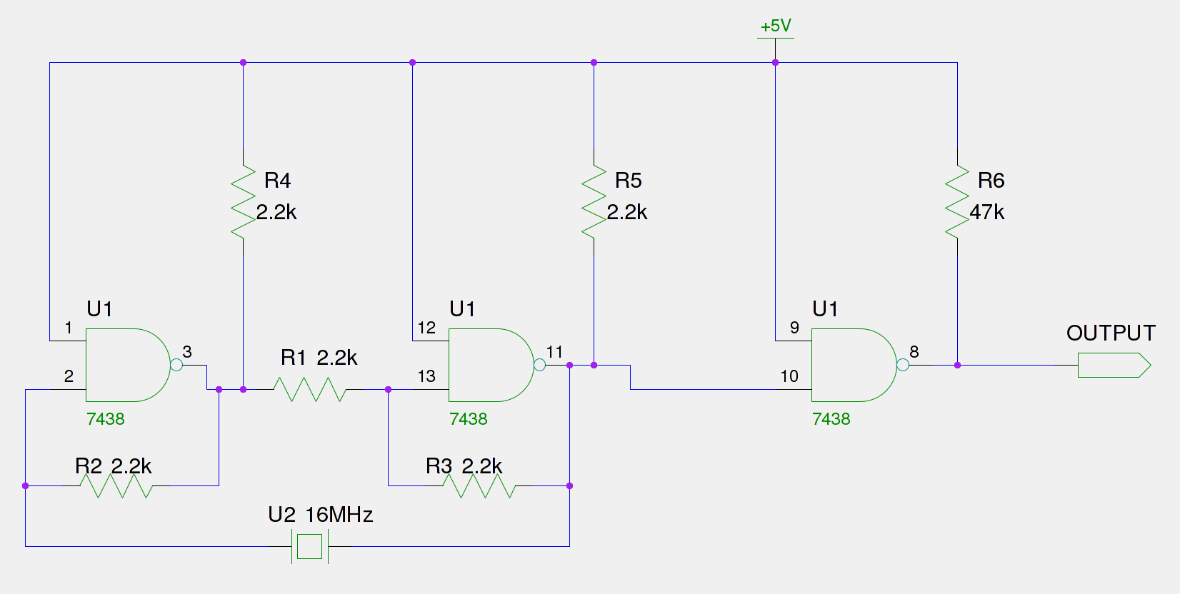
An old Eistar SJ-1 digital pulser has been acquired. However, the frequency it generates is consistently 66% of the expected output. The frequency observed at the frequency stage (Pin 11) is 66% of the 16 MHz crystal, which equates...