
Frequency meter circuit

The described circuit operates by applying an input signal to a gate, which subsequently drives a counter for a defined period. The timing of the signal is crucial for the operation of the system. Once the counting period elapses, the input signal is halted temporarily, allowing the counter's output to be captured and stored in buffer memory. This stored data is then displayed, providing a visual representation of the count achieved during the active signal period.
The timing base, composed of two integrated circuits, generates the necessary signals (COUNT, LE, RESET) to control the operation of the counter. The initial design has a cycle time of 2 seconds, which may be too long for certain applications. Adjustments to the timing parameters Tle and Treset can effectively reduce the overall cycle time, although this might necessitate the addition of more ICs or a transition to a microcontroller-based solution for enhanced flexibility and control.
The PIC16F84A microcontroller is chosen for its programming simplicity and efficiency in power consumption. The code written for this microcontroller initializes the necessary ports and sets the timing intervals for the counting process. The program includes specific wait times, allowing for accurate timing of the signal transitions. The use of specialized ICs like the MMC22926 enables the system to handle frequencies up to 6 MHz, ensuring that the counter can operate effectively within this range.
For applications requiring higher frequency processing, the introduction of an ECL or ACH divider at the input stage of the gate can facilitate the handling of faster signals, thus expanding the operational capabilities of the circuit. This design provides a robust framework for signal counting applications, combining the reliability of integrated circuits with the flexibility of microcontroller programming.The input signal it is applied to a gate G and then to a counter, for a precisely period of time After this period of time, the input signal it is stopped for a while and then the cycle it is repeated. In the time of break the content of counter it is transferred in buffer memory and then it is displayed.
After the load of buffer memory, the con tains of counter is reset of reason to can begin a new count cycle. The successions of this signals are conform the follows diagram : The signals COUNT, LE, RESET are generated from the base of time. A very simple base of time which contains 2 ICs can be build using the folow schematic: Unfortunately this schematics have a long time of cycle Tc = 2s.
In order to make this time shorter we can modified only the times Tle and Treset. But that means to use more CIs or another solution is to use a microcontroller with the necessary software. I have used a PIC microcontroller type PIC16F84A because it is easy to programm and the power consumption is low.
The program is written for the PIC16F84A but cheaper PICs (as PIC16C61) can be used. ;= Base of time =18/06/00= ; rb0 1s ; rb1, rb2. 75ms ; internal clock ; standard crystal 4 MHz XT ; ;- ; configure programmer list p=16f84A;f=inhx8m _CP_OFF equ H`3FFF` ;code protect off _PWRTE_ON equ H`3FFF` ;Power on timer on _WDT_OFF equ H`3FFB` ;watch dog timer off _XT_OSC equ H`3FFD` ;crystal oscillator _CONFIG _CP_OFF & _PWRTE_ON & _WDT_OFF & _XT_OSC ;- ; cpu init portb equ 06 count1 equ 0C count2 equ 0D count3 equ 0E ;- ; bit init w equ 0 f equ 1 ;- org 0 ; ;- init movlw 0 tris portb ; set portb as output movwf portb start bsf portb, 0 ;rb0=1 call pause ;wait 1s bcf portb, 0 ;rb0=0 bsf portb, 1 ;rb1=1 call pauza ;wait. 75 ms bcf portb, 1 ;rb1=0 bsf portb, 2 ;rb2=1 call pauza ;wait. 75 ms bcf portb, 2 ;rb2=0 goto start pause movlw. 8 ; load count3 with decimal 8 movwf count3 d3 movlw. 250 ; load count1 with decimal 250 movwf count1 d1 movlw. 165 ; load count2 with decimal 165 movwf count2 nop ; compensation 1us d2 decfsz count2, f ; decrement and skip next line if zero goto d2 ; if not zero decfsz count1 ; decrement count1 if count2 is zero goto d1 ; do inside loop again if count1 nz decfsz count3 ; decrement count3 if count1 is zero goto d3 ; do inside loop again if count3 nz retlw 00 pauza movlw.
250 movwf count1 lop1 decfsz count1, f goto lop1 retlw 00 ;- end ;= Download project from here. For the counter I have used two specialized IC`s type MMC22926, that works up to 6 Mhz, the National Semiconductor alternative to MMC22926 is 74C926. If a higher frequency is need to be processed, a ECL or ACH divider can be used at gate input. 🔗 External reference
Related Circuits

This circuit is designed to provide automatic current limiting up to 8.4 A. Unlike traditional current limiters that rely solely on a resistor, this circuit minimizes voltage drop until a specified current threshold is exceeded. The current limit can...
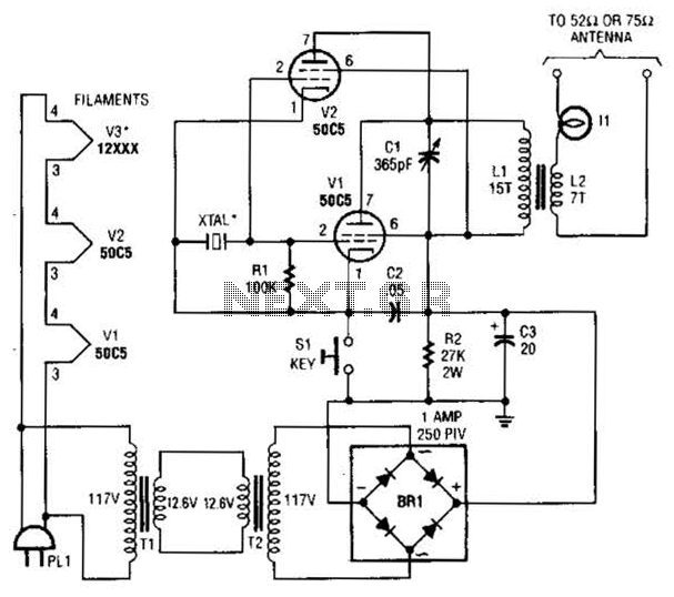
This low-power video transmitter is designed for remote control (R/C) applications, surveillance, or amateur radio purposes. It utilizes seven transistors within a crystal oscillator-multiplier RF power amplifier chain, along with a high-level video modulator. A supply voltage of 9...
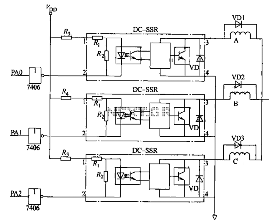
The figure illustrates that the DC Solid State Relay (SSR) in the input stage functions as an opto-isolator. When the switch output is high, the driver circuit inverts this signal to low. This process involves a light-emitting diode (LED)...
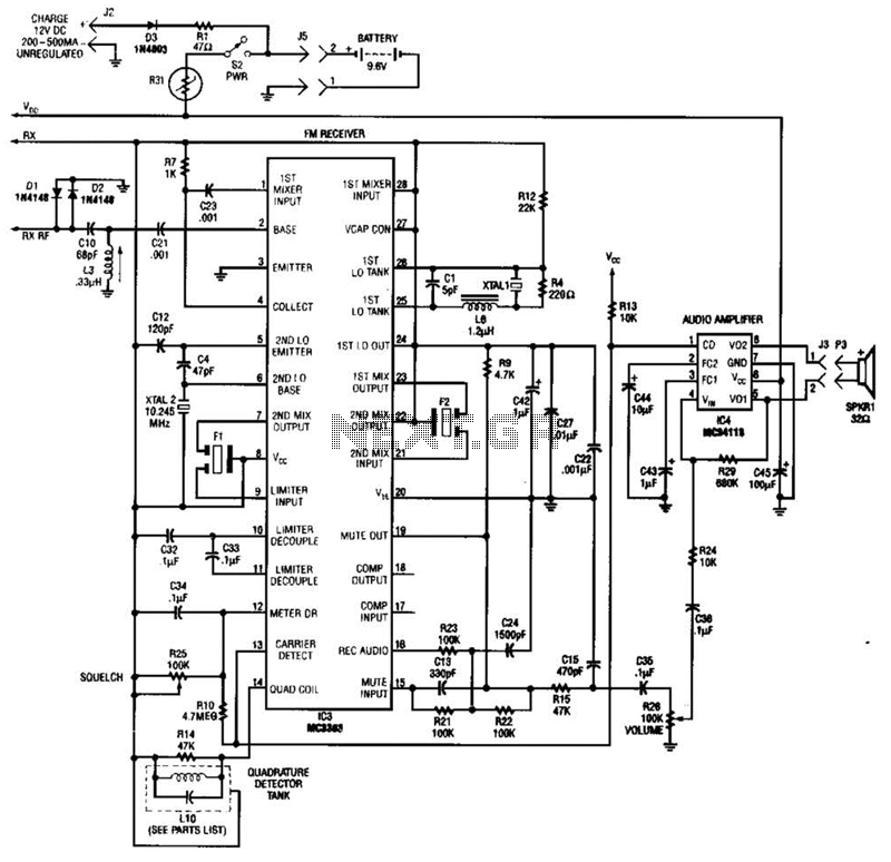
Using a Motorola MC3363 LSI one-chip FM receiver, the circuit is a dual-conversion FM receiver with a 10.7-MHz IF chain. IC4 provides power to drive a small speaker. The described circuit employs the Motorola MC3363 integrated circuit, which is designed...
This circuit differs from similar circuits in view of its simplicity and a totally different concept of generating the control signals. Usually remote control circuits make use of infrared light to transmit control signals. Their use is thus limited...
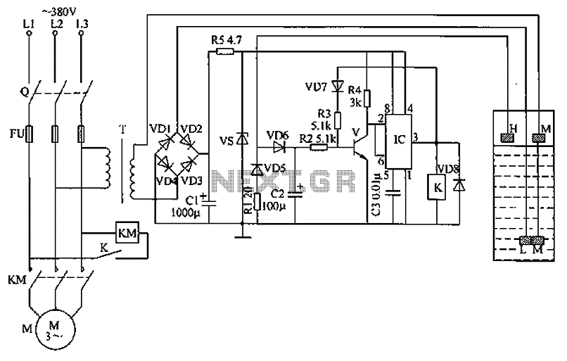
The circuit functions as a liquid level automatic controller, comprising a power circuit, a level detection circuit, and a control execution circuit. The power circuit includes a knife switch (Q), fuse (FU), power transformer (T), rectifier diodes (VD1 to...