
Frequency Modulated FM Oscillator Circuit

The FM oscillator is an essential component in various communication systems, particularly in wireless audio transmission and microphone applications. It operates by varying the frequency of the output signal in accordance with the amplitude of the input audio signal, allowing for the transmission of audio information over radio waves.
The circuit typically consists of a voltage-controlled oscillator (VCO) that generates a carrier frequency, which is modulated by the input audio signal. Key components include a transistor or integrated circuit configured to produce the oscillation, along with passive components such as resistors, capacitors, and inductors that determine the frequency range and stability of the oscillator.
In applications where regulatory compliance is required, such as part-15 devices, the oscillator must maintain a stable frequency while minimizing harmonic distortion and ensuring that the output power remains within specified limits. The design may also incorporate feedback mechanisms to enhance stability and performance, ensuring that the FM oscillator can reliably operate under varying conditions.
Additionally, careful consideration of power supply decoupling and grounding techniques is crucial in minimizing noise and interference, which can adversely affect the quality of the transmitted audio signal. Overall, the FM oscillator serves as a vital building block in modern wireless communication systems, enabling efficient and high-quality audio transmission.This FM oscillator can be used for wireless audio, microphone and part-15 applications where stable frequency modulated oscillators is needed. Lt can be va.. 🔗 External reference
Related Circuits
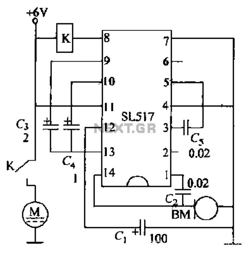
Electric cars utilize a voice circuit principle, where sound signals are captured by a microphone (BM) and processed. The signal is then coupled through a capacitor to an integrated circuit (IC), which includes an internal amplifier that boosts the...
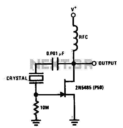
The JFET Pierce crystal oscillator accommodates a broad frequency range of crystals without requiring circuit modifications. The JFET gate does not load the crystal, which preserves a high quality factor (Q) and ensures excellent frequency stability. The JFET Pierce oscillator...
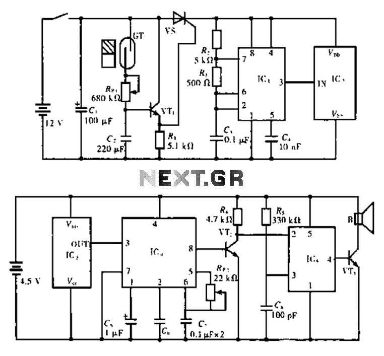
The alarm circuit is composed of two main components: the transmitter and the receiver. The transmitter circuit, as illustrated in Figure A, features a smoke break reed switch labeled GT. When a magnet approaches the GT, the internal contacts...
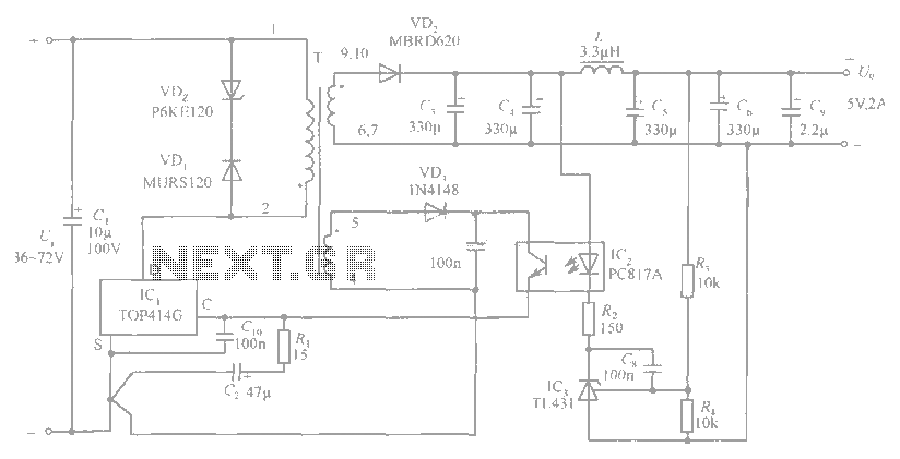
The circuit diagram includes an input filter capacitor C1 and a primary clamp composed of VDz and VD1. The resistor R1 is connected to the control terminal. C2 serves as a bypass capacitor. The TOP414GC-S is connected in parallel...
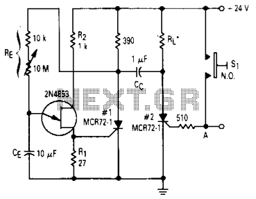
After one cycle of operation, SCR1 will be activated, resulting in a low voltage being applied to the UJT emitter circuit, which interrupts the tuning function. When pushbutton SI is pressed, or a positive pulse is applied at point...
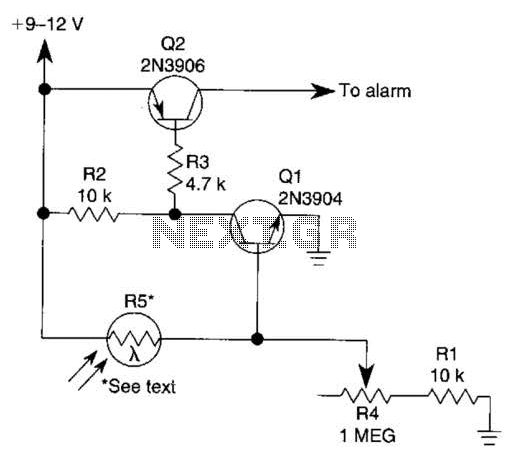
The circuit functions as a sensor capable of triggering an alarm without direct contact from an intruder. It utilizes a visible or invisible light source that illuminates the sensor, maintaining the detection loop in a normally closed state. As...