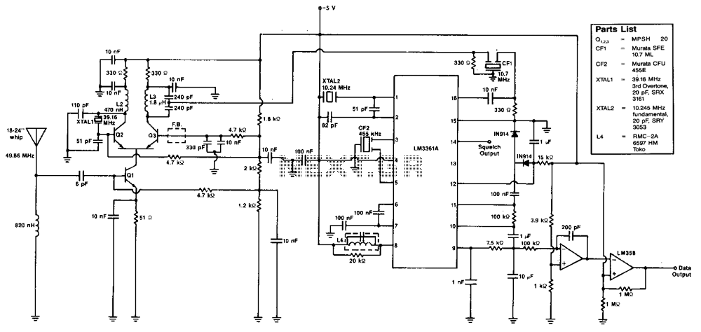
Fsk-data-receiver

The various signal frequencies are obtained for an incoming carrier centered at 49.86 MHz. The receiver employs double conversion, with intermediate frequencies (i-fs) at 10.7 MHz and 455 kHz. Ceramic filters are used in both intermediate frequencies for selectivity and reduced coil count. A quadrature detector is used to recover the baseband data, and an integrator and Schmitt trigger are utilized to filter the demodulated output. Additionally, a squelch circuit acts as a status line, and the open-collector output switches high when a signal is received. The LM3361A functions as the second local oscillator (LO), second mixer, limiting intermediate frequency, quadrature detector, and squelch, while consuming less than 4 mA from a 5-V logic supply. The entire receiver requires approximately 10 mA.
The described receiver circuit operates effectively within the specified frequency range, utilizing a double conversion architecture to enhance selectivity and sensitivity. The first stage of conversion processes the incoming carrier signal at 49.86 MHz, which is subsequently mixed down to an intermediate frequency of 10.7 MHz. This initial mixing is typically accomplished using a first mixer, which may employ a diode or transistor-based architecture for efficient signal processing.
The second conversion stage further reduces the frequency to 455 kHz, utilizing the LM3361A as the second local oscillator and mixer. The choice of ceramic filters at both intermediate frequencies is crucial as they provide high selectivity with a compact design, minimizing the complexity and size of the circuit by reducing the number of inductive components required.
The quadrature detector is pivotal in the demodulation process, allowing for the extraction of baseband data from the modulated signal. This component typically employs a pair of mixers and phase-shifted signals to achieve accurate demodulation. Following the quadrature detection, an integrator is used to smooth the output signal, while a Schmitt trigger ensures clean transitions and noise immunity in the digital signal output.
The squelch circuit plays an important role in the overall functionality of the receiver, providing a means to mute the output in the absence of a received signal. Its operation is indicated by an open-collector output that transitions to a high state when a valid signal is detected, thus signaling the presence of a carrier.
The LM3361A, with its low power consumption of less than 4 mA from a 5-V supply, is well-suited for battery-operated or low-power applications. The overall current draw of approximately 10 mA for the entire receiver indicates efficient design, making it ideal for portable communication devices where power efficiency is a critical concern. This combination of features and components results in a robust receiver capable of effective signal processing in a variety of communication applications.The various signal frequencies are obtained for an incoming carrier centered at 49.86 MHz. The receiver employs double conversion, with i-fs at 10.7 MHz and 455kHz. Ceramic filters are used in both i-fs for selectivity and reduced"coil count. A quadrature detector is used to recover the baseband data, and an integrator and Schmitt trigger are used to filter the demodulated output. Also included is a squelch circuit that functions as a status line, and the open-collector output switches high when a signal is received.
The LM3361A functions as the 2nd LO, 2nd mixer, limiting i-f, quadrature detector, and squelch; yet, it consumes less than 4 mA from a 5-V logic supply. The entire receiver requires approximately 10 mA.