
Function generator

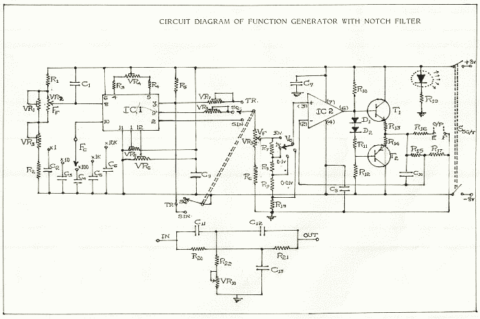
The described circuit is a waveform generator capable of producing square and triangle waves, commonly utilized in various applications such as signal processing, audio synthesis, and control systems. The first stage, which mimics a comparator, utilizes positive feedback to create hysteresis, ensuring stable switching between high and low states. This configuration minimizes noise susceptibility and enhances the reliability of the output signals.
The inverting input's biasing at half the Vcc is crucial for determining the threshold levels at which the circuit toggles between its output states. The feedback mechanism, where the output is routed back to the non-inverting input, is integral for controlling the oscillation frequency. This feedback loop allows for precise frequency modulation, which is essential in applications where timing is critical.
The amplitude of the square wave output, specified as 8 V peak-to-peak, indicates the maximum voltage swing of the first stage, which is vital for ensuring the generated signals are robust enough for downstream applications. The second stage's role as an op-amp integrator allows it to convert the square wave into a triangle wave, providing a linear ramp signal that can be advantageous in various signal processing tasks.
Resistor R3, as the input element, plays a significant role in determining the circuit’s response to input signals, while capacitor C1, serving as the feedback element, influences the integrative properties of the second stage. The relationship between resistors R1 and R2 is critical, as it directly affects the amplitude of the triangle wave in relation to the square-wave output, allowing for flexibility in waveform shaping.
The formula governing the frequency of oscillation for both waveforms is essential for designers and engineers to understand, as it allows for precise control over the generated frequencies, ensuring they meet the requirements of the specific application. Overall, this circuit exemplifies the integration of comparator and integrator functionalities to produce versatile waveform outputs.The circuit has both square-wave and triangle-wave output. The left section is similar in function to a comparator circuit that uses positive feedback for hysteresis. The inverting input is biased at one-half the Vcc voltage by resistors R4 and R5. The output is fed back to the non-inverting input of the first stage to control the frequency. The amplitude of the square wave is the output swing of the first stage, which is 8 V peak-to-peak. The second stage is basically an op amp integrator. The resistor R3 is the input element and capacitor Cl is the feedback element. The ratio R1/R2 sets the amplitude of the triangle wave, as referenced to the square-wave output. For both waveforms, the frequency of oscillation can be determined by the equation:
Related Circuits
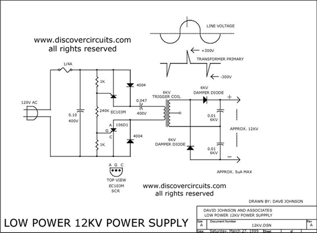
The 12kV High Voltage Generator utilizes a unique adjustment to generate approximately 12,000 volts with a current of about 5 µA. It consists of two SCRs forming two triggering circuit paths. These SCRs discharge a 0.047 µF, 400V capacitor...
The documents, software, tools, and links are provided to enhance the capabilities of electronics students, hobbyists, or professionals by sharing information. This information and the associated links should be utilized by website visitors at their own risk and responsibility....
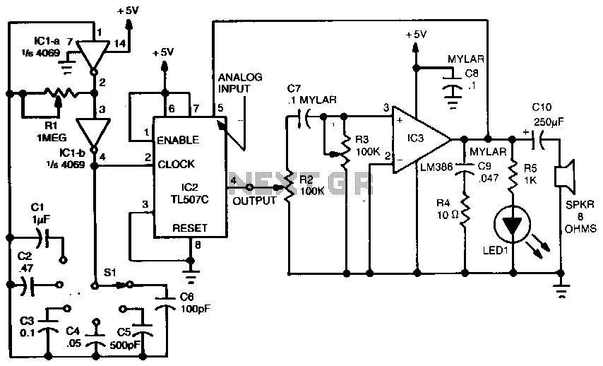
A variable dock-pulse generator consists of two sections of IC1, which is a 4069 CMOS hex inverter, along with resistor R1, switch S1, and capacitors C1 through C6. By adjusting R1 and switching one of the capacitors into the...
Quartz crystals exhibit a property where their amplitude and phase characteristics repeat at uneven multiples of their fundamental frequency. Overtone crystals are specifically cut to enhance this property. Any crystal can be utilized at one or more of its...
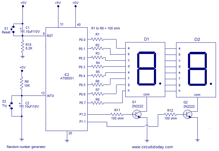
A simple random number generator utilizing the 8051 microcontroller. The AT89S51 is the controller employed in this setup. The circuit design for the random number generator based on the AT89S51 microcontroller involves several essential components and connections. The AT89S51 microcontroller,...
The first positive pulse from a classic 555-based oscillator is always 1.6 times longer than the subsequent pulses. This discrepancy occurs because, during the initial cycle, capacitor C2 begins charging from 0 V. While this is typically not an...