
Function-generator

The interconnecting leads from the 741 operational amplifier pins 2 and 3 to their respective resistors should be kept short, ideally less than 2 inches, as longer leads may induce oscillation. The full output swing is achievable up to about 5 kHz; beyond this frequency, the output begins to diminish due to the slew rate limitations of the 741 operational amplifier. At 20 kHz, the output swing is expected to be around 20 V, ±10 V. This issue can be addressed by substituting the 741 with an operational amplifier that has a higher slew rate, such as the LF356.
This waveform generator circuit utilizes a 741 operational amplifier configured in a function generator topology. The circuit is capable of producing multiple waveform types by utilizing different configurations of resistors and capacitors. The sine wave output is typically generated using a Wien bridge oscillator configuration, while triangular and square wave outputs can be achieved through integrator and comparator stages, respectively.
The power supply section is designed to convert the 110 Vac input to a suitable DC voltage level for the operational amplifier. This is typically accomplished using a transformer to step down the voltage, followed by a rectifier and filtering stage to provide a stable DC supply.
To ensure optimal performance, careful attention must be given to the selection of components, particularly the operational amplifier. While the 741 is a widely used general-purpose op-amp, its slew rate limitations may restrict performance at higher frequencies. The LF356, with its enhanced slew rate, is recommended for applications requiring higher frequency outputs without significant distortion.
Furthermore, the layout of the circuit should minimize lead lengths to reduce parasitic capacitance and inductance, which can contribute to unwanted oscillations and signal degradation. Proper decoupling of power supply lines is also essential to maintain signal integrity, particularly in high-frequency applications.
In summary, this waveform generator is a versatile instrument capable of producing various waveform types across a wide frequency range, with specific design considerations necessary to optimize its performance and reliability.This generator will supply sine, triangular, and square waves from 2Hz to 20kHz. This complete test instrument can be plugged into a standard 110 Vac line for power. VoVT will be up to ±25 V (50 V pk-pk across loads as small as 10 0 (about 2.5 A maximum output current). Capacitor working voltages should be greater than 50 V de and all resistors should be 112 W, unless otherwise indicated.
The interconnecting leads from the 741 pins 2 and 3 to their respective resistors should be kept short, less than 2 inches if possible; longer leads might result in oscillation. Full output swing is possible to about 5kHz; after that the output begins to taper off because of the slew rate of the 741, until at 20kHz the output swing will be about 20 V,p± 10 V.
This problem can be remedied by simply using an op amp with a higher slew rate, such as the LF356.
Related Circuits
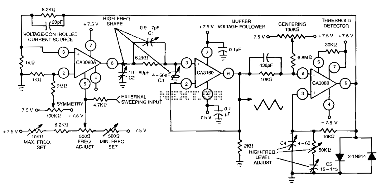
This function generator features an adjustment range exceeding 1,000,000 to 1 and utilizes a CA3160 BiMOS operational amplifier as a voltage follower. It incorporates a CA3080 operational transconductance amplifier (OTA) as a high-speed comparator, alongside another CA3080 configured as...
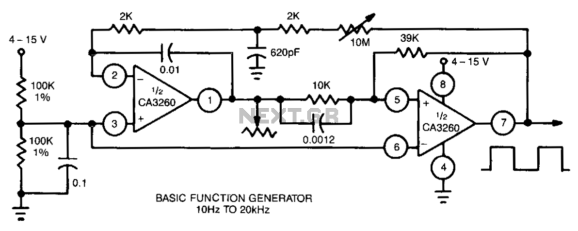
This function generator utilizes a CA3260 BiMOS operational amplifier to perform both integrator and switching functions. A 620-pF capacitor and a 2-kΩ resistor are employed to shape the feedback square wave, minimizing spikes. The device covers the full audio...
This generator will supply sine, triangular, and square waves from 2Hz to 20kHz. This complete test instrument can be plugged into a standard 110 Vac line for power. VoVT will be up to ±25 V (50 V pk-pk across...