
Fuzz box 5

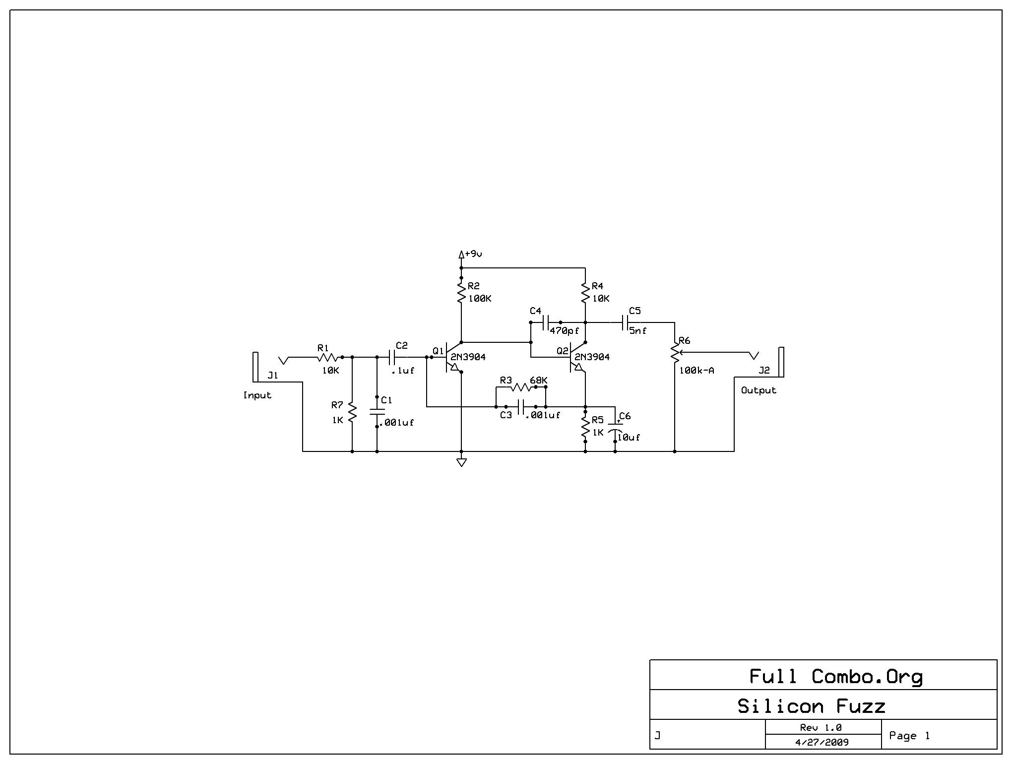
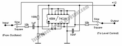
The circuit utilizes two transistors, Q1 and Q2, configured in a cascading arrangement to achieve significant signal amplification. The choice of transistors will depend on the required frequency response and gain characteristics. In this configuration, both transistors operate in their active regions, ensuring that the signal is amplified without distortion until the point of overload is reached. This overload point is particularly relevant when interfacing with high-output devices such as electric guitars, which can produce signals that exceed the linear operating range of the amplifying stage.
RV1 serves as a variable resistor, allowing the user to adjust the feedback loop within the circuit. By modifying the resistance of RV1, the amount of feedback can be fine-tuned, which directly influences the overall voltage gain of the circuit. A higher resistance setting on RV1 will reduce the feedback, leading to an increase in gain, while a lower resistance will enhance feedback and decrease gain. This feedback mechanism is crucial for controlling the distortion characteristics of the output signal.
The output of the circuit is designed to produce a squared version of the input signal. This squaring effect is a result of the non-linear response of the transistors when driven into saturation. The degree of squaring can be adjusted by varying RV1, allowing for flexibility in shaping the output waveform. This feature is particularly useful in applications where specific tonal qualities are desired, such as in guitar effects pedals.
Overall, this circuit design is an effective method for amplifying and shaping audio signals, providing musicians with a tool to manipulate their sound creatively. Proper component selection and tuning of RV1 will ensure optimal performance and versatility in various audio applications.Transistors Q1 and Q2 amplify the incoming signal, and the gain is such that the input will overload when used with an electric guitar. RVl adjusts the amount of feedback present, and hence voltage gain. The output is, therefore, a squared version of the input signal The amount of squaring is varied by RVl.
Related Circuits
This circuit helps eliminate surplus small AC mains adapters from a desktop. It is a practical DC power supply box powered directly by the SMPS of a desktop PC. The output provides regulated, clean, and protected +12VDC. Additionally, a...
A Direct Injection (or DI) box is a very handy piece of equipment for any public address rig or recording studio, whether for band or general use. It will allow you to connect the output from guitar amps, keyboard...
All components function correctly. The final software comprises 930 lines of assembler code. ProTel was utilized to create the final circuit diagram. The design has been streamlined to a single chip, with the PIC microcontroller performing all tasks. It...
After constructing the Mighty Mite amplifier project, it became apparent that an additional element was needed to enhance its character. A Hendrix-style fuzz face was considered to add an edge to the tone while allowing for character during low-volume...
Prior to emailing Pablo Gian Villamil, he provided a link to his class notes on generating polyphonic sound with Arduino. Efforts were made to understand his circuitry through various blog posts and component listings, including the CMOS Hex Schmitt...
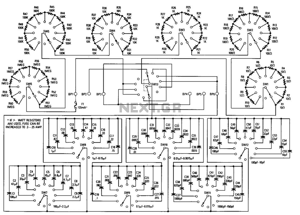
This decade box can be configured for any resistance value between 10 and 11.1 in 10-stop increments. A switch is employed to set various RC configurations. It is recommended to utilize precision components in the circuit. If feasible, verify...