
G STRAIN ENERGY ABSORBER

The circuit involves three transistors, designated as Q1, Q2, and Q3, which are critical in the operation of a G Strain absorber circuit. It is essential that these transistors do not operate in an astable mode, which would typically generate square wave outputs. Instead, the expected output should exhibit a non-linear waveform when observed on an oscilloscope, particularly between the designated points XB, YB, and ZB. This requirement indicates that the circuit is designed for a specific function that relies on the transistors' ability to amplify signals without oscillating in a predictable square wave pattern.
The transistors selected for this application have a current gain (hfe) ranging from 35 to 40. This gain is crucial for the circuit's functionality, as it must remain below a threshold of 70 to ensure stability and proper operation. The uniformity of the transistor gain across all three devices is also emphasized, suggesting that variations in gain could lead to undesirable circuit behavior or performance issues.
For the power supply, it is indicated that a high power supply is required, although the specific voltage and current ratings are not provided in the description. It can be inferred that the power supply must be capable of supporting the load requirements of the circuit while maintaining the necessary voltage levels for the transistors to function effectively.
In summary, the design of this G Strain absorber circuit hinges on the careful selection and configuration of transistors Q1, Q2, and Q3, ensuring they operate in a non-oscillatory manner while maintaining a low and consistent gain. The power supply must be robust enough to support the circuit's demands, ultimately contributing to the overall performance and reliability of the system.It is important to know that transistors Q1,Q2,Q3 must not work like an astable (tri-phase) multivibrator (you could verify it on scope (no square waves but NON LINEAR wave between XB, YB, ZB must be displayed on the scope). The transistors used have gain between 35-40, it is important to notice that the transistor gain must be low (< 70 ). To succeed your G Strain absorber circuit, you must have transistor gain (hfe) approximately equal. The power supply must be a high po 🔗 External reference
Related Circuits
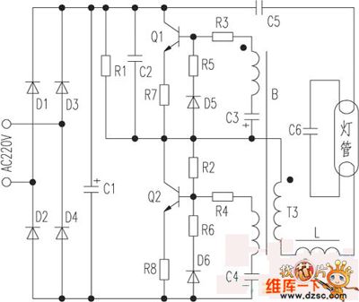
The optically-controlled circuit plays a crucial role in urban street lighting and corridor illumination. By utilizing this circuit, lighting lamps can be automatically turned on and off based on ambient light levels, thereby reducing the need for manual control,...
Every innovation begins with a simple everyday problem, such as watching an IPL match on TV when suddenly the power goes out, prompting the search for an alternative way to watch via mobile network. Similarly, a frequent issue of...
The silicon carbide (SiC) MOSFET offers notable advantages, including a straightforward drive circuit. It possesses unique characteristics that render it a superior switching device in comparison to traditional options. The silicon carbide MOSFET is a type of field-effect transistor that...
The development of a solar energy street lamp control device has progressed through three stages. The first generation featured a simple and crude function, allowing the light to be turned on or off, but required connection to a light-sensitive...
The saving lamp circuit features two main types: glass cover and exposed. The glass cover variants include three series: spherical, cylindrical, and processing types. The first two series consist of four variations: transparent, carved, engraved, and white. These lamps...
The Testatika design, based on the Pidgeon/Wimshurst machine, represents one type of electrostatic generator that can be used to construct this system. Since the early 1900s, such power generators have significantly evolved in terms of sophistication and power output....