
Gain-Controlled Amplifier

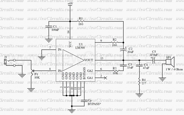
The described circuit utilizes the LM1894 integrated circuit, which is designed for automatic gain control (AGC) in audio applications. The primary function of this circuit is to ensure that audio output levels remain consistent despite variations in ambient noise levels.
In operation, the circuit begins with sound waves being captured by a microphone, which converts the acoustic signals into an electrical signal. This signal is then coupled to pin 6 of the LM1894 through a 0.1 µF capacitor. The capacitor serves to block any DC offset from the microphone, allowing only the AC audio signal to pass through. The LM1894 processes this audio input to determine the appropriate gain level needed based on the detected ambient noise.
The variable-gain amplifier (VGA) within the LM1894 adjusts the audio gain dynamically. When the environment is quiet, the gain is reduced, resulting in a lower audio output at pin 11. Conversely, in a noisy environment, the gain increases, amplifying the audio output to ensure it is audible. The amplified output is then taken from pin 11, which is also connected through another 0.1 µF capacitor. This output capacitor serves to filter out any DC component from the amplified signal, providing a clean audio output suitable for further processing or amplification.
The design of this circuit is particularly useful in applications where ambient noise levels can fluctuate significantly, such as in public address systems, hearing aids, or any audio device that requires adaptive volume control. This ensures optimal performance and user experience by maintaining audio clarity and consistency across varying environmental conditions. This single-chip circuit adjusts its audio gain according to the ambient noise picked up by the microphone. When operating in a quiet environment, the audio output is quiet, while a noisy environment results in a louder audio output. Audio to pin 13 is amplified by the variable-gain amplifier within the LM1894 IC. Audio from the microphone connected through 0.1-/iF capacitor to pin 6 controls the audio gain of the variable-gain amplifier.
The output appears on pin 11 and is taken off through an 0.1-/xF capacitor.
Related Circuits
More: The input data lacks specific content, providing only placeholders without any detailed information. In the context of electronic schematics, a comprehensive description typically involves detailing the components, their interconnections, and the overall functionality of the circuit....
This circuit is a mono audio amplifier that will boost low frequencies as you see at the frequency response. The circuit is suitable for driving a subwoofer speaker for example. The output power of the circuit is about 1...
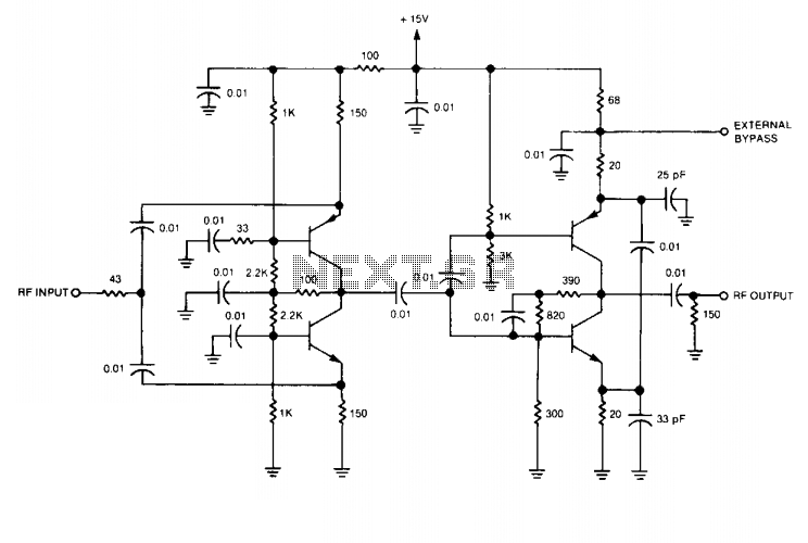
This wideband RF isolation amplifier has a frequency response of 0.5 to 400 MHz ± 0.5 dB. This two-stage amplifier can be utilized in applications that require high reverse isolation, such as receiver intermediate-frequency (IF) strips and frequency distribution...
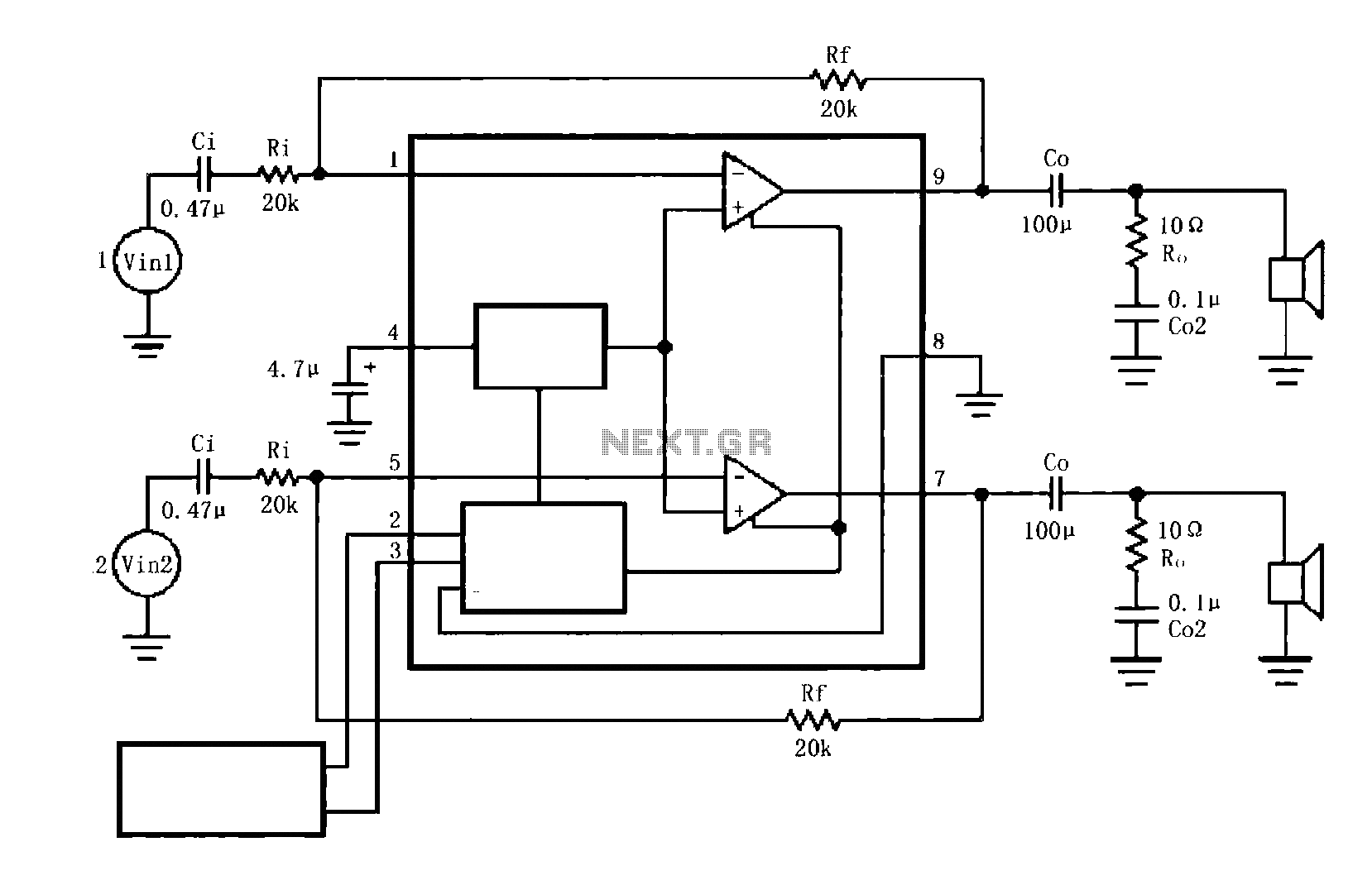
The circuit illustrated is a typical configuration for the LM4916 two-channel amplifier. The left and right channel audio signals are fed into the LM4916, which amplifies them internally. The output is then delivered through a coupling capacitor (Co) to...
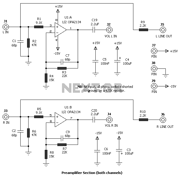
The amplifier drives a pair of loudspeakers using two LM3876 integrated power amp ICs (50 watts per channel), or a pair of headphones via a Meier crossfeed filter and an OPA2134 dual opamp. It provides four switchable line level...
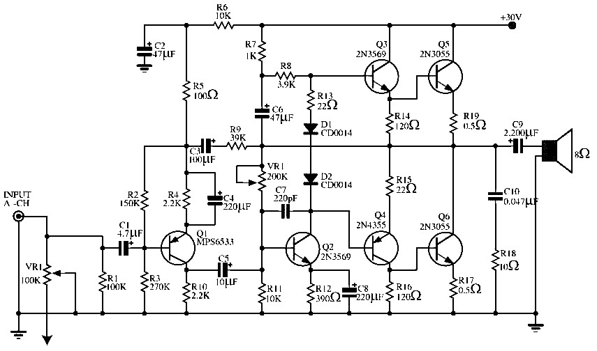
This circuit does not function as effectively as it could. It was created when the designer had a limited understanding of circuit design. An improved schematic will be developed and posted later, featuring a better design. The schematic indicates...