
gps tracker project gps module jp module lcd dispaly

The project involves assembling various components, including the GPS module, microcontroller, and display, according to the provided schematic. After connecting the components, the code must be uploaded to the microcontroller for the system to function correctly. The GPS module outputs several data strings per second, including the essential RMC string, which provides the necessary positional information. The standard output rate is 4800 baud. The GPS module operates at 3V serial levels, which can be directly connected to the USART receive input on a PIC microcontroller. Configuring the USART to 4800 baud, with 8 data bits and 1 stop bit, allows for the reception of each character, which the code subsequently processes.
To successfully create a GPS tracking module, knowledge in several areas is essential. This includes understanding microcontroller programming, interfacing with serial communication protocols, and familiarity with GPS technology and its data formats. Students should also be adept at reading datasheets for components and troubleshooting potential issues during assembly and coding. Building a GPS module from scratch is a complex task that typically requires advanced skills and access to specialized equipment. It is advisable to utilize commercial GPS modules to simplify the development process while still achieving the desired functionality.A GPS tracker demonstration program with data logging capacity. It uses BasicStamp 2P (also you can use PIC chip) to interface with a GPS Module, JP Module and 16x2 LCD display. Sample code used is standard PBasic 2. 5 ( It can be changed to PicBasic or PicBasic Pro very easy). It can record GPS data to a MMC/SD card with latitude and longitude information. The data can be processed from Google Map at the website:. If you have Google Earth installed, the data also can be processed into a KML file (Google earth data file format) at the website: hi. u know what. ur project would be very helpful to me. coz we have been given the same project for our final year. but the problem is. i have been told to make the module of GPS myself. now can you pz let me know as to what all things may be necessary to study to make this possible. and whethr it is possible to be made on our own. plz reply soon. thanx. tc I think I have already posted all of information ( including manufactures and parts datasheet) for this project.
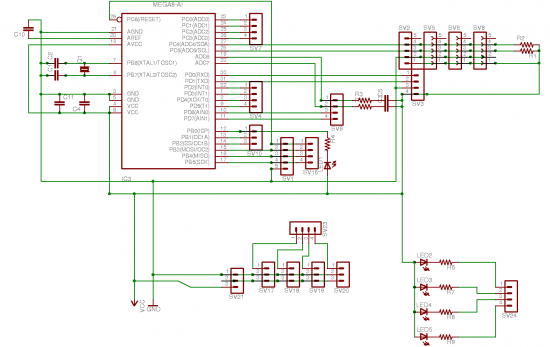
You can follow the project schematic put every parts togather, load the code to MCU. It should work. hi. u know what. ur project would be very helpful to me. coz we have been given the same project for our final year. but the problem is. i have been told to make the module of GPS myself. now can you pz let me know as to what all things may be necessary to study to make this possible. and whethr it is possible to be made on our own. plz reply soon. thanx. tc What do you have at your disposal In all likelihood you do not have the capability to build it yourself without using a GPS module. The 2GHz satellite signal is far beyond the ability of many engineers, never mind students, even with the appropriate ICs in hand.
Unless you have a $10K+ prototyping system capable of double sided plate through PCBs and are capable and willing to solder 0. 5mm pitch 100 pin ICs for 5-10 prototype runs to work out the bugs do not even bother. All GPS receivers that I have used will output several strings each second. All you need to do is apply power to the GPS receiver and the data strings start being sent. One of those is the RMC string which tells you all you usually need for position. The usual rate is 4800 baud. If you can connect to the 3 V serial level from the GPS, that can be connected directly to the USART receive input on a PIC.
If you set the USART to 4800 baud, 8 bits, 1 stop bit, it should receive each character, and then the code takes each character from the USART. 🔗 External reference
Related Circuits
This device has been designed as a demonstration application of an expandable system of modules for constructing mobile robots, adhering to the standards discussed in the Society of Robots forum. These modules can interconnect using an I2C bus, and...
Hackers listen up. Everyone understands and enjoys the utilitarian benefits that GPS has brought to our lives but what if it didn’t work any more? I suppose you could build some sort of surface to space missile robot that...
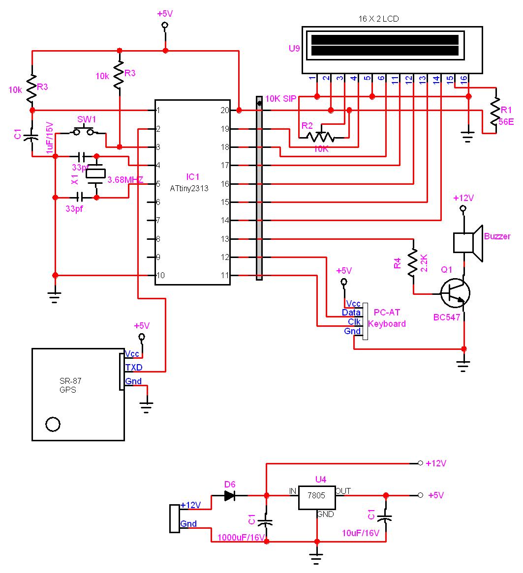
In this project, a GPS module is interfaced with an AVR microcontroller. The ATtiny2313 retrieves location data from the GPS and displays it on an LCD screen. The project involves the integration of a GPS module with the ATtiny2313 microcontroller,...
An LCD essentially comprises two glass plates with a layer of liquid crystal material sandwiched between them. The LCD utilizes an electrically controlled light-polarizing liquid. The liquid crystal display (LCD) operates based on the manipulation of light through liquid crystals,...
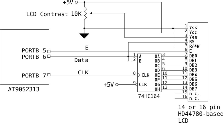
If no characters are displayed on the LCD and the hardware and software have been verified as functional, adjust the LCD Contrast potentiometer until the characters become visible. To send an 8-bit character or command to the LCD via...
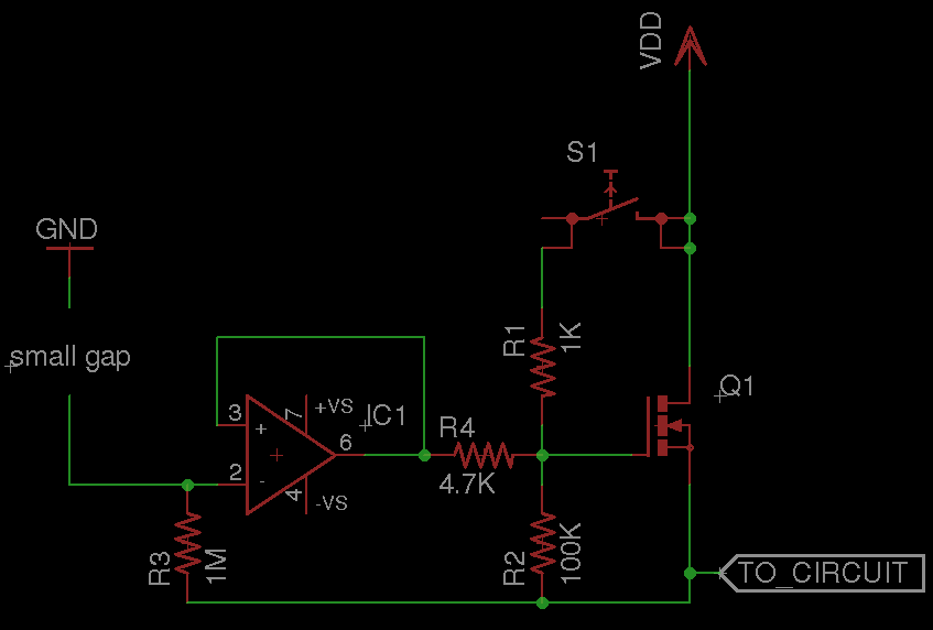
A circuit that requires protection from high voltage. Is there a component other than a fuse that does not need to be replaced every time? Something like a switch that activates only when high voltage is supplied, diverts the...