
Guitar tube amplifier Peavey schematic

The provided description indicates modifications to an existing electronic circuit. The changes involve the replacement of certain parameters and components as denoted by color coding. Specifically, values that were previously marked in blue have been substituted with new values represented in red. This suggests a recalibration or adjustment of the circuit's operational characteristics, potentially enhancing its performance or aligning it with new specifications.
Additionally, the removal of blue components signifies that certain elements of the circuit have been deemed unnecessary or obsolete, thereby streamlining the design. The introduction of red components indicates the addition of new elements that likely serve a specific function, possibly improving the circuit's efficiency or expanding its capabilities.
The mention of moving the relay mute contacts to the other side of capacitor C21 suggests a potential redesign of the circuit layout. This alteration could be aimed at optimizing the physical arrangement of components to minimize interference, improve accessibility, or enhance signal integrity. The relay mute contacts are crucial for controlling audio signals, and repositioning them could lead to better performance in applications such as audio processing or signal routing.
Overall, these modifications reflect a systematic approach to circuit design, emphasizing the importance of adaptability and precision in electronic engineering. The adjustments made to values and components, along with the proposed layout change, are indicative of a thorough evaluation of the circuit's functionality and an intent to refine its overall design.Blue VALUES replaced by values in RED. Blue COMPONENTS removed from circuit. Red components added to circuit. Optional: move relay mute contacts to other side of C21. 🔗 External reference
Related Circuits
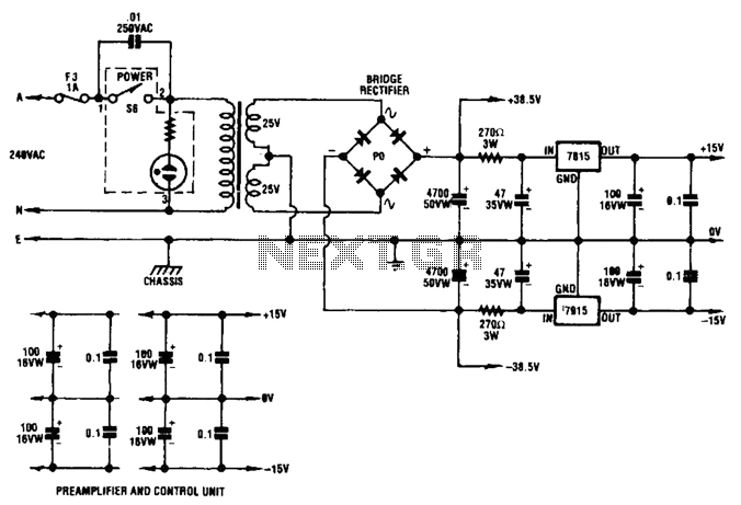
A dual audio amplifier that delivers 50 W per channel is illustrated in the schematic. It features a preamplifier and tone controls, as well as a headphone amplifier. The circuit also shows a power supply providing 38.5 V and...
Most thefts occur after midnight when individuals enter the second phase of sleep known as paradoxical sleep. An energy-saving circuit has been designed to deter thieves by illuminating potential entry points, such as the kitchen or backyard, around 1:00...
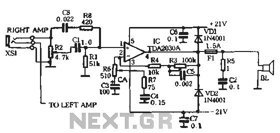
The circuit comprises two main components: the Lisheng power amplifier and the rectifier filter section. The stereo audio power amplifier circuit diagram, depicted in Figure 5-85, illustrates only one channel, with the other channel being identical. The audio signal...
The schematic diagram presented is of a twin "T" phase shift oscillator, an audio oscillator. This oscillator derives its name from the phase shift network formed by resistors R3, R4, and capacitors C1, C2, and C3. This network shifts...
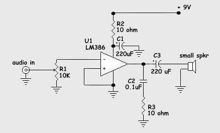
This preamp is very simple, and will work under tough conditions. The input impedance is pretty high, so it won't load down electric guitars. It will also amplify microphones. When there is a moment, there will be some additions that...
The circuit utilizes two 2N3819 FETs arranged in a cascode configuration. The lower FET functions in common source mode, while the upper FET operates in common gate mode, achieving full high-frequency gain. The lower FET is tunable, enabling peak...