
H Bridge design for robotics and motion control systems

H-bridges are widely utilized in robotics and motor control applications to enable bidirectional control of DC motors. An H-bridge consists of four switches arranged in a configuration that allows current to flow in either direction through the motor, facilitating forward and reverse rotation. The low-side switch element specifically refers to the switches connected to the ground side of the motor circuit.
In a typical H-bridge configuration, two low-side switches are employed, which are often implemented using MOSFETs or bipolar junction transistors (BJTs). When one low-side switch is turned on, it completes the circuit, allowing current to flow through the motor in one direction. Conversely, activating the other low-side switch reverses the current flow, enabling the motor to rotate in the opposite direction. This control method is essential for applications requiring precise motor direction and speed control.
The low-side switch configuration offers several advantages, including simpler drive circuitry and reduced complexity in the control logic. Additionally, it helps to minimize the risk of shoot-through conditions, which can occur if both high-side and low-side switches are activated simultaneously. Proper design considerations must be made regarding the gate drive signals to ensure that the switches are turned on and off at the appropriate times, preventing damage to the components and ensuring efficient operation.
In summary, the low-side switch element in an H-bridge plays a critical role in the effective control of motors in robotic applications. Its ability to manage current flow direction is fundamental to achieving the desired motion control, making it a vital component in modern robotics and automation systems.H bridge applications for robots, robotics, and motor control. This post focuses on the low side switch element. 🔗 External reference
Related Circuits
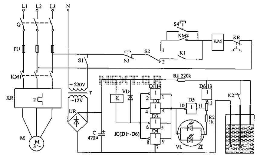
The liquid level automatic controller circuit consists of a power circuit, a control instruction level detection circuit, and a starter control circuit. The power circuit is formed by a power transformer, a rectifier bridge, and a filter capacitor. The...
Understanding how to program the PIC microcontroller in theory is beneficial; however, practical learning occurs when the code is executed on a PIC within a circuit. One can either construct a new circuit for each test or utilize a...
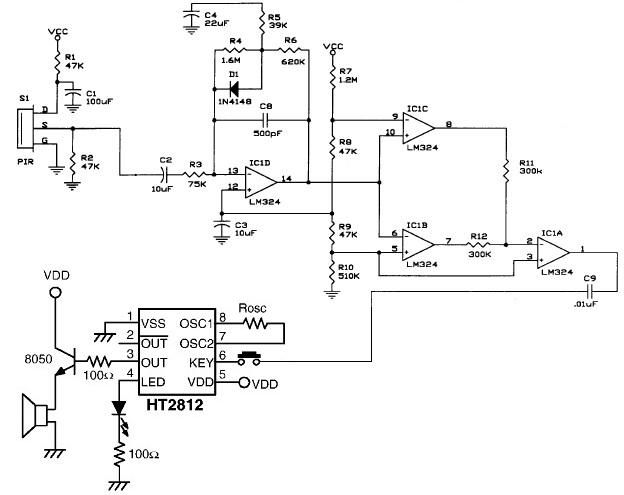
The operational amplifier IC1D modifies the frequency response to enhance the frequencies generated during motion detection while eliminating others, such as noise or gradual temperature variations. When the output voltage of IC1D exceeds 1.67V, it activates pins 8 and...
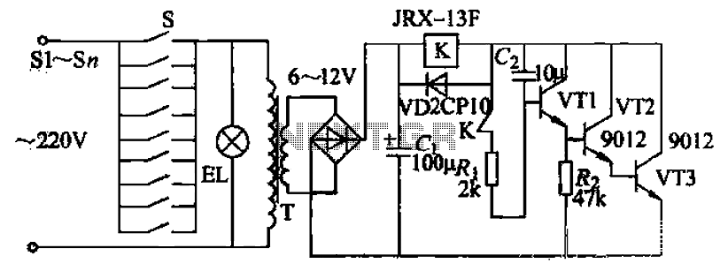
Pressing the button switch Sl-Sn activates the circuit, turning on the transformer T. The low-voltage alternating current from the secondary winding is directed to a bridge rectifier and a filter capacitor Ci, which produces a DC voltage. This voltage...
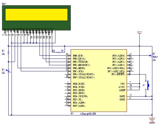
A straightforward tutorial on utilizing the ADC (Analog to Digital Converter) unit of the AVR microcontroller, demonstrated with the Atmega8, including a circuit diagram and code examples. The ADC unit in the Atmega8 microcontroller is a crucial component that allows...
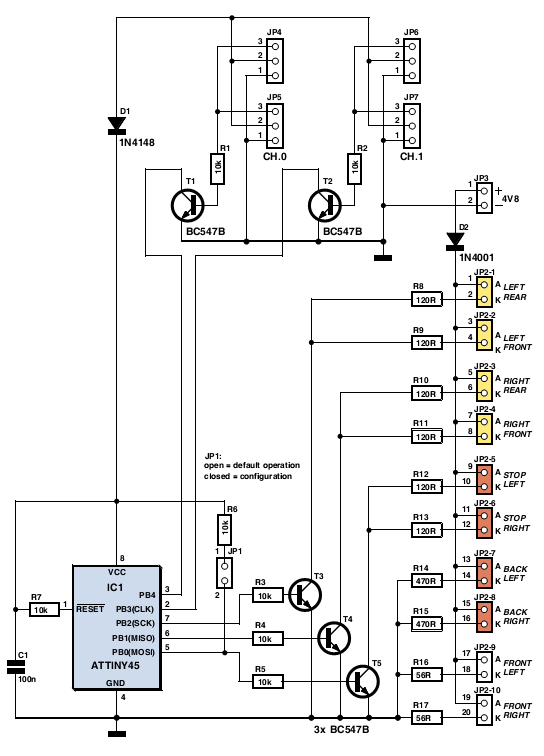
The author gifted a radio-controlled (RC) model car to his partner. She enjoyed it but suggested that adding realistic lights would enhance the experience. Consequently, the author returned to his workshop, utilized his soldering iron, and began outfitting the...