
Hakko 936 ceramic heater A1321
The circuit design for the soldering station in question is fundamentally straightforward, primarily consisting of a power supply, a control board, and the heating element. The power supply typically converts AC mains voltage to a lower voltage suitable for the control circuitry and heating element. The control board regulates the power delivered to the heating element based on feedback from the temperature sensor, ensuring stable operation and preventing overheating.
The temperature sensor, likely a thermocouple or thermistor, provides feedback to the control board about the current temperature of the heating element. This feedback loop is crucial for maintaining the desired operating temperature. In the case of clone heaters, the sensor's low resistance may indicate a malfunction or degradation, which could lead to inaccurate temperature readings and compromised performance.
Modification of the circuit to accommodate a different heating element, such as a genuine Hakko heater, may require recalibrating the control board to account for the new heater's characteristics, including its resistance and thermal response. This recalibration could involve adjusting the software parameters or replacing specific components within the control circuitry to ensure compatibility.
The integration of a microcontroller for automated testing could enhance the evaluation of heating elements significantly. This microcontroller could be programmed to cycle through various temperature settings, recording heat-up times and performance metrics for each type of heating element tested. Such data would provide valuable insights into the efficiency and reliability of different heating solutions, informing future purchasing decisions and modifications to the soldering station.
Overall, careful consideration of the components, their specifications, and their compatibility is essential for optimizing performance and ensuring longevity in soldering applications.Crap, the sensor on my clone is low resistance and the replacement heater is 45 Ohms. Is there anywhere you can buy the clone heaters or modify the station to accomodate the genuine heater Going home for the holiday week but the circuit inside last I looked was pretty basic, might be possible to swap some resistors and re-cal it for the new heate r No clue what the official circuit looks like so maybe it`s not so simple. Crap, the sensor on my clone is low resistance and the replacement heater is 45 Ohms. Is there anywhere you can buy the clone heaters or modify the station to accomodate the genuine heater Going home for the holiday week but the circuit inside last I looked was pretty basic, might be possible to swap some resistors and re-cal it for the new heater No clue what the official circuit looks like so maybe it`s not so simple. I just want to add my findings to the "Grade Fail" heater. They are not fake they are just cheap clones that are NOT to be used with Hakko 936 stations. Electrically incompatible with the Hakko. They are actually Nichrome coil winding heaters and covered with a ceramic sleeve. These heaters are prone to breakage especially at the tip. And they don`t like to be over driven, any more than 24vac it will be broken. I have seen numerous types where the coil length is different. So they perform drastic different. If you have this type of heaters, avoid at all cost. They are at the bottom food chain, it will actually cost you more in the long term, despite their cost.
You can buy a clone Hakko control board and `upgrade` your station along with those clone heating elements. There is another type of stainless metal sleeve heating element. It is made in Taiwan, it is compatible with those Nichrome winding ceramic heaters. These stainless heaters are very robust and will last 2-4 few years at 24x7. I have collected numerous types of heating elements over the years. There are plenty of "GRADE A" Hakko ceramic compatible clones. All of them perform very well. In case you are wondering, I use 4 at one time to heat up my DIY 200W heatplate. Works like a charm. I would recommend them if you can`t find the genuine heater. Most if not all of the hot air stations use a mains powered heater already, and cheap unregulated irons all do, so I guess it isn`t that odd.
They can probably get a lot more power and cheaper, since there`s no transformer. I can`t read the label on the socket but it might be a warning that this is a mains-powered iron, not a bad idea. It looks like the iron is still grounded so there shouldn`t be a shock hazard, although one problem they might have is with buyers being a little reluctant with "Why is it so light inside.
" Next I took Macro photos of the printing on the heating elements, the first two pictures are genuine, the rest are clones. It`s very easy to tell, the Hakko printing is very thick and pretty. Next, I tried measuring the sensor resistance vs temperature, it was very tricky I didn`t want to connect the sensor to the control board because it might introduce error, and that means I have to control the temperature manually.
Well, I hooked up a push button in series with the 24vac transformer and that did it. I was hard trying to `stabilise` the temperature but I soon get the hang of it. The thermocouple sensor was sandwiched with the heating element by a piece of copper. The sensor resistance reading is taken by 4 wire 34401 to reduce lead resistance error and temperature readout via Fluke 187 and a thick K thermocouple which acts as a thermal buffer so it sinks those heat spikes. Unfortunately I was only able to do 5 sets, it was a tedious and slow process. But I think it should be enough as soon as I saw the graph. The clones behave similar to the Hakko. I might rig up a automatic microcontroller based test jig that measures heatup times between temperatures.
When I get some more free time. The resistance is less l 🔗 External reference
Related Circuits
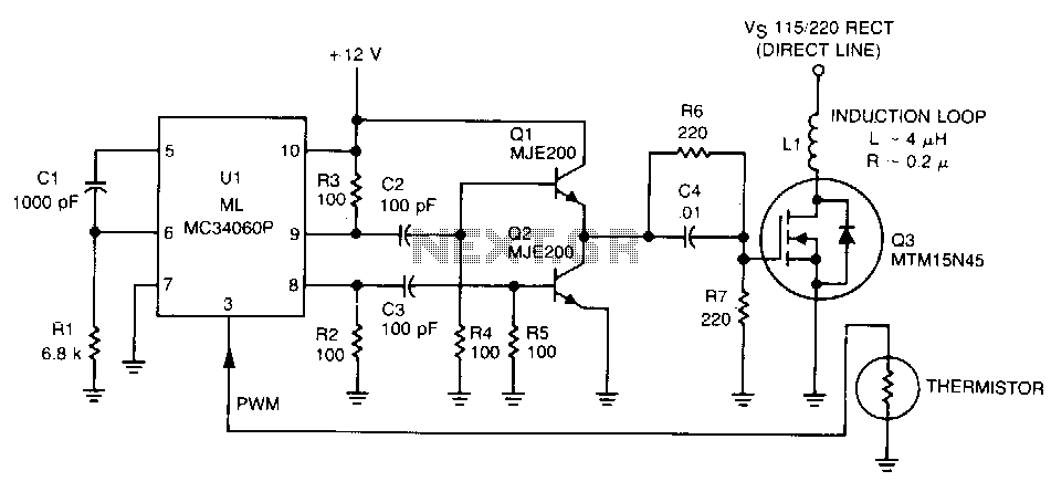
Variable width pulses with fast rise times are generated by the UL and MC34060 operating at 120 kHz, which is the optimal frequency for heating aluminum alloy containers. The pulse width is modulated by monitoring the temperature of the...
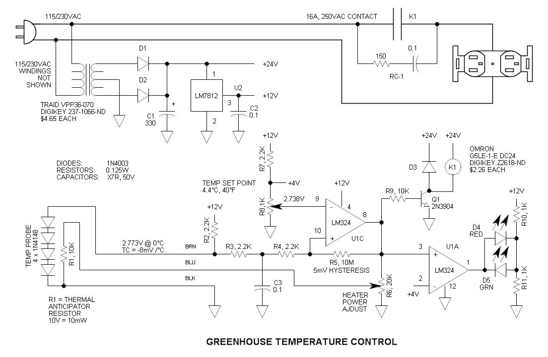
This circuit consists of four 1N4148 diodes connected in series with a thermal anticipation resistor (R1) heat-shrunk together at the end of a three-wire signal cable, which is visible in some photos. The thermal anticipation resistor is an old...
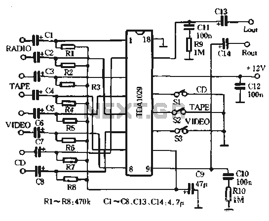
The AV combination as depicted in the diagram involves the first stage using the Philips TDA1029, which functions as a four-input switching signal processor. The second stage employs the NE5532 as a preamplifier, while the B of the NEC,...

A second piece of information has recently come to light regarding an original Rife machine schematic associated with Dr. O. C. Gruner of Canada, who collaborated with Rife in the 1930s to isolate a fungal form of Rife's cancer...
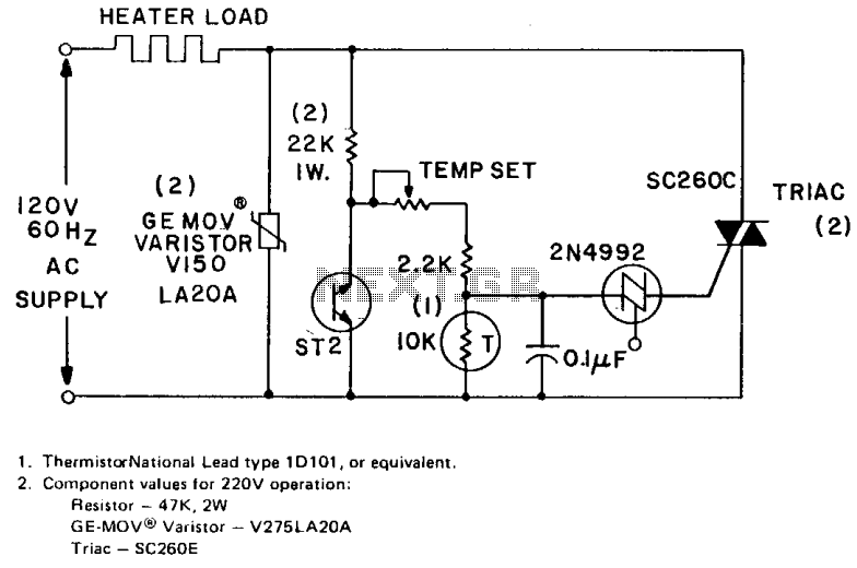
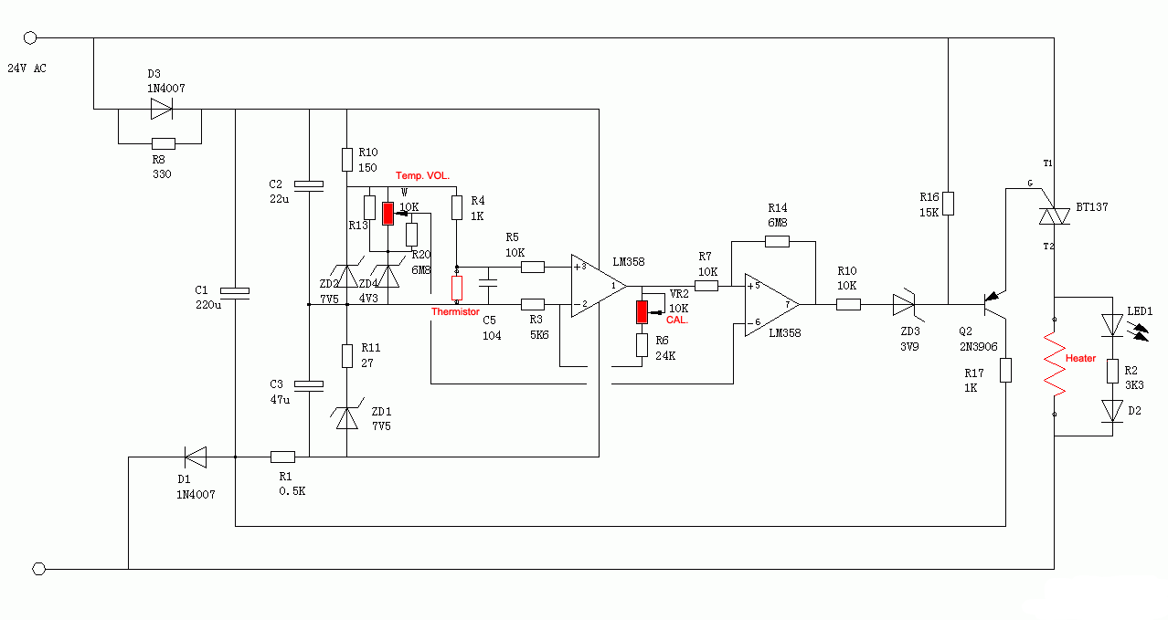
The circuit can control up to 6 kW of heating with moderate gain using a 25-amp triac (SC260D). Feedback is provided by a negative temperature coefficient (NTC) thermistor, which is positioned near the environment being temperature controlled. The temperature...
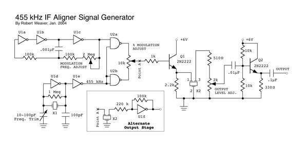
The resonator appears to be highly susceptible to harmonics. For instance, if the resonator frequency is set at 455 kHz, it also permits frequencies at 910 Hz, 1820 kHz, and 3.640 MHz, which seems to be dominant. Frequencies around...