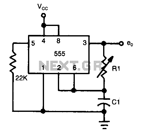
Half-duty-cycle-oscillator

The frequency of oscillation depends on the Rl/Cl time constant, allowing for frequency adjustment by varying Rl. This is a basic circuit.
The described circuit operates based on the relationship between resistance (Rl) and capacitance (Cl), which together form a time constant that directly influences the frequency of oscillation. In this configuration, Rl represents the resistance in ohms, while Cl denotes the capacitance in farads. The time constant (τ) is calculated as τ = Rl * Cl, where τ indicates the time it takes for the circuit to charge or discharge to approximately 63.2% of its maximum voltage.
The frequency of oscillation (f) can be derived from the time constant using the formula f = 1 / (2πτ). This relationship implies that by adjusting the resistance Rl, one can finely tune the oscillation frequency of the circuit. Increasing Rl will lead to a longer time constant, subsequently lowering the frequency of oscillation, while decreasing Rl will shorten the time constant and increase the frequency.
This basic circuit can be implemented using a simple RC oscillator configuration, which typically includes a resistor (Rl), a capacitor (Cl), and an operational amplifier or a comparator to generate a square wave output. The output frequency can be observed on an oscilloscope or through a frequency counter, providing a visual representation of the adjustments made to Rl.
In practical applications, this circuit can be utilized in various electronic devices requiring precise timing or frequency generation, such as signal generators, timers, or audio tone generators. The simplicity of the design allows for easy integration into larger systems, making it a versatile choice for engineers seeking to implement frequency modulation in their projects.Frequency of oscillation depends on the Rl/Cl time constant and allows frequency adjustment
by varying Rl. This is a basic circuit.