
Handball

A simple single-player PONG game utilizing an LED matrix was developed, focusing on the synchronization of signals as observed in an analog PONG game previously constructed. Initially, a 10x10 matrix was envisioned for the ball, leading to the selection of the LM3914 dot/bar driver (operating in dot mode for this game) with an analog input for counting operations.
During the design phase, an error was identified in the logic for reversing the ball's direction upon reaching the end of a row or column. The signal processing was too rapid, preventing the end LED from illuminating sufficiently before the ball changed direction. Consequently, the LED matrix was reduced to 8x8 LEDs, allowing the first and last output of the LM3914 to serve as the direction-reversing signal. However, during circuit assembly, the first output remained continuously active, necessitating either a further reduction to a 7x7 LED matrix or the introduction of a time delay (approximately 1/3 to 1/2 second) on the second output of the LM3914 to enable the end LEDs to light up. The latter approach was selected, successfully demonstrating horizontal movement using a 555 timer for the delay.
The vertical movement circuit was also designed, but the paddle controller and the related logic for collision detection at the bottom of the matrix required development first. The paddle controller was implemented using another LM3914, configured with four outputs corresponding to four paddle positions, and a potentiometer connected between 5V Vcc and ground to serve as a voltage divider, with the wiper connected to the input of the chip.
Collision detection logic between the ball and the paddle was more complex. With only four paddle positions corresponding to four columns in the ball's matrix, and eight possible column positions for the ball, four OR gates were incorporated for every two ball columns. When the ball occupied either column of the paddle's two-LED-wide column, the output would be HIGH (1). The OR gates were constructed using two diodes and a pull-down resistor, ensuring a LOW (0) output in the absence of input signals.
Subsequently, AND gates were utilized to combine the OR gate outputs with the paddle positions. For example, if the paddle was in column 1 and the ball was also in column 1, the AND gate output would be HIGH (1). If the columns did not match, the AND gate output would be LOW (0). The outputs from the four AND gates were consolidated through three OR gates to generate a single signal that would go HIGH when the ball entered the paddle's column.
To reverse the vertical motion of the ball, another AND gate was employed, using both the column match detection signal and the bottom row signal from the LM3914. This setup ensured the ball would only bounce off the paddle when it was at the bottom row and in the correct column. However, due to the persistent activation of the bottom row signal from the LM3914, the second row output was routed to a time delay circuit. Additional pull-down resistors and inverters were incorporated to ensure correct logic input configurations.
If the first output of the LM3914 could be made to function correctly, the time delay circuits would be unnecessary, allowing the reverse signal to be derived directly from output 1 instead of the delayed output 2. The inputs of the LM3914 are analog; therefore, a 4013 dual flip-flop, along with two capacitors (one for vertical and one for horizontal movement), was employed to generate the required analog voltage signals. Each capacitor was connected to 5V (Vcc) through a 1K and a 5K potentiometer to adjust the X/Y speeds, ensuring the capacitor charged upon powering the game. The reversing signals from the LM3914 and the time delays were interfaced with the Set and Reset inputs of the 4013. The output was connected to an NPN transistor, which was configured in parallel with the capacitor through the 5K potentiometer, allowing for either capacitor charging or discharging. When the output of the 4013 transitions to HIGH, triggered by the 10th output of the LM3914 for either the X or Y position, the system responds accordingly.A simple single player PONG game using a LED matrix while thinking about how the sync signals logically worked together in the Analog Pong Game I had built. I originally wanted a 10X10 matrix for the ball, and tried to think of some chips capable of counting up and down and chose the LM3914 dot/bar (dot mode used in thisgame) driver with an analog input.
During the designing stage, I learned of a mistake in the concept of reversing the ball`s direction when it reached the end row/column because the signal goes through the logic FAST and would barely give the end LED sufficent time to glow before the ball reverses direction. So the LED matrix was cut down to 8x8 LEDs, and the first and last output of the LM3914 could be used as the reversing signal.
Unfortunately, when the circuits were built the first output stays on the whole time, and I was unable to figure out why so it was either cutting the matrix down to 7 by 7 LEDs or putting an approximately 1/3 to 1/2 second time delay on the second output of the LM3914s to allow the end LEDs to glow. I chose the latter method and got a successful test on the horizontal movement using a 555 timer for the delay.
The vertical circuit was built, but first the paddle controller and the associated logics has to be built for collision detection at the bottom. The paddle controller was simply another LM3914 with only four outputs wired for the four paddle positions, and a simple pot between 5V Vcc and ground as a voltage divider with the swiper connected to the input of the chip.
The associated logics for collision detection between the ball and the paddle is a bit tricky. First of all, there are only four paddle positions, thus four columns on the ball`s matrix. However, the ball has 8 possible column positions so four OR gates are inserted on every two ball columns and whenever the ball is in either column in the paddle`s current two-LED long column, the output is HIGH (1). The OR gates are simply two diodes and one pull-down resistor, so the output is naturally LOW (0) without any input signals.
Next, there are AND gates that combine the OR gate signals with the position of the paddles. For instance, if the paddle is in column 1 and the ball is in column 1, the AND gate outputs HIGH (1). If the column of either the ball or paddle do not match, the AND gates output LOW (0). The outputs of the four AND gates are all combined by three OR gates to create a single signal that goes HIGH whenever the ball enters the paddle`s column.
The last thing to do is to use another AND gate using the column match detection signal and the bottom row signal of the LM3914 to reverse the vertical motion of the ball. That way the ball has to be at the bottom row and in the right column to bounce off the paddle. However, because the bottom row signal from the LM3914 is always on for some reason, the 2nd row output is sent to another time delay circuit.
Several pull-down resistors and inverters were necessary to ensure the inputs of the logic were done correctly. If you can get output 1 on the LM3914 to work then no time delay circuits are necessary and the reverse signal would be obtained from output 1 rather than the delayed output 2.
The inputs of the LM3914s are analog so I used a 4013 dual flip-flop, two capacitors (one for vertical and one for horizontal) to generate the analog voltage signals. The capacitor is connected to 5V (Vcc) via a 1K and a 5K pot for variable X/Y speeds so the capacitor always charges up when you turn the game on.
The reversing signals from the LM3194 and time delays are fed into the Set and Reset inputs of the 4013. The output is hooked up to a NPN transistor that is in parallel with the capacitor through the 5K pot to either allow the capacitor to charge or discharge.
When the output of the 4013 goes HIGH as a result of the 10th output of the LM3914 for either X or Y position going HIGH, the 🔗 External reference
Related Circuits
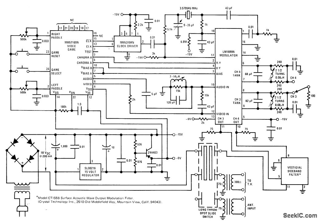
The circuit utilizes the MM57100 TV game chip from National Semiconductor to generate logic for backgrounds, paddles, a ball, and digital scoring. It produces all necessary timing signals, including sync, blanking, and burst, to interface directly with the antenna...