
Hands-off-intercom
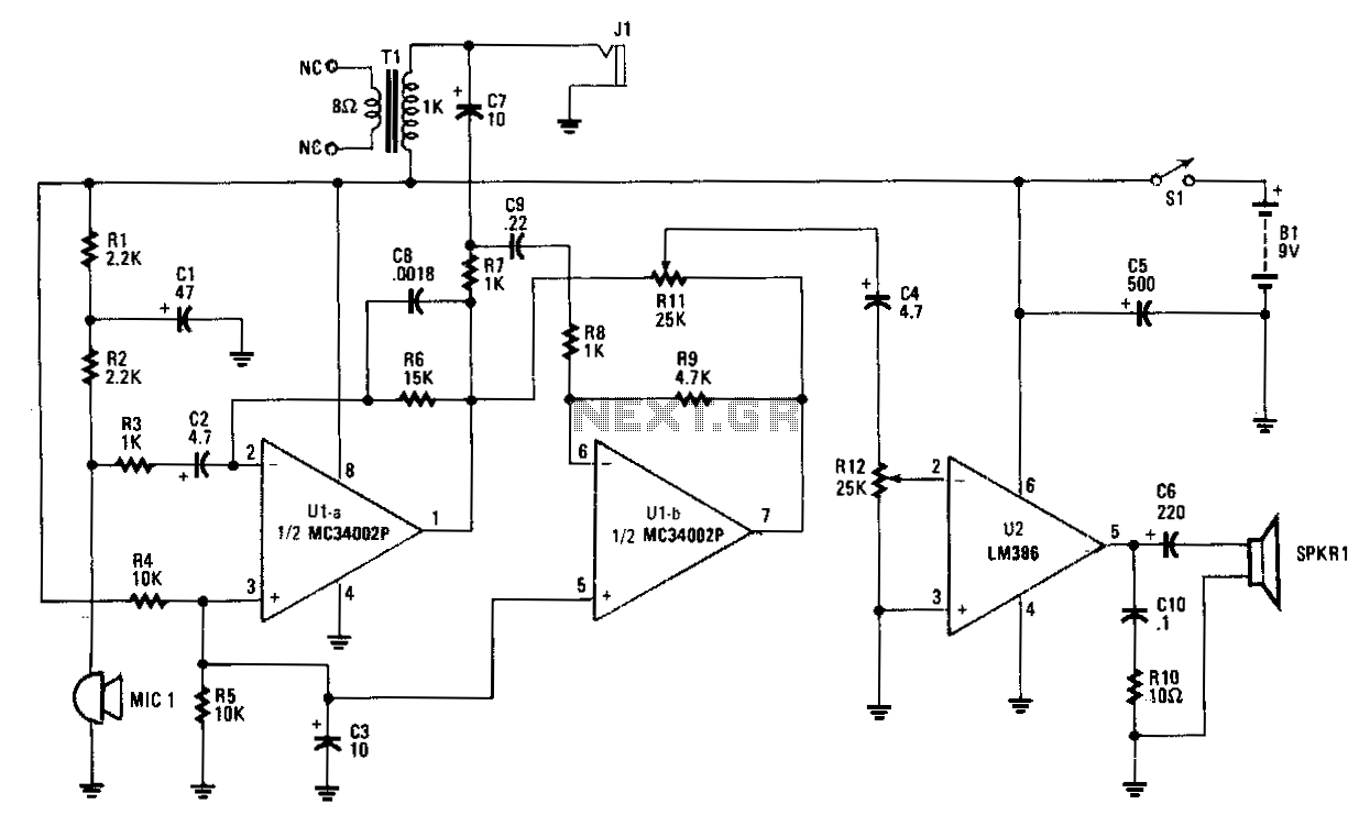
Amplifier A increases the microphone's output to a usable level. The output signal is fed to op amp B, which inverts the signal by 180 degrees. A balance-control potentiometer connects across the outputs of amplifiers A and B. If an audio tone is fed into the microphone and the balance potentiometer's wiper is fully positioned toward the A output, the tone will be heard at a high level. As the wiper is rotated toward the B output, the audio level will decrease until it nearly disappears near the center of the potentiometer's range. Continuing to rotate the wiper will cause the signal to increase again. With the balance control set for minimal output, the intercom's tendency to self-oscillate from acoustic feedback between the microphone and speaker is minimized. The microphone's amplified signal at the output is fed to the other intercom through the audio in/out cable. Since both intercom units are identical, the audio information from one unit is fed into the input of op amp B in the other unit. The incoming audio is slightly amplified by op amp B, and the output signal is sufficiently increased by the power amplifier to drive the speaker.
The circuit described involves a two-stage amplification process utilizing operational amplifiers (op amps) and a balance-control potentiometer. The initial signal from the microphone is amplified by Amplifier A, which ensures that the audio signal is at an appropriate level for processing. The output from Amplifier A is then routed to op amp B, which serves a dual purpose: it inverts the audio signal by 180 degrees and prepares it for further amplification.
The balance-control potentiometer plays a critical role in managing the audio output levels from both amplifiers A and B. By adjusting the wiper of the potentiometer, the user can control the relative contributions of the two signals. When the wiper is directed fully toward the A output, the amplified audio signal is at its maximum, allowing clear audio playback. Conversely, as the wiper is moved toward the B output, the signal from Amplifier A is gradually attenuated, approaching silence at the center position. This feature allows for fine-tuning of the audio balance, which is particularly useful in minimizing feedback loops that could lead to self-oscillation, a common issue in intercom systems.
The output from the microphone is not only amplified but also transmitted to another intercom unit via an audio in/out cable. This connection facilitates the sharing of audio signals between identical intercom units, ensuring that the audio information is effectively communicated. The incoming audio signal at the second unit is again processed by op amp B, which provides a slight amplification before the signal is sent to a power amplifier. The power amplifier is responsible for driving the speaker, ensuring that the audio output is sufficiently loud for clear reception.
Overall, this circuit design effectively manages audio signals in an intercom system, providing both amplification and balance control to enhance user experience while minimizing feedback issues.Amplifier A increases the microphone"s output to a usable level. The output signal is fed to op amp B, which inverts the signal180°. A balance-control potentiometer connects across the outputs of amplifiers A and B. 1f an audio tone is fed into the microphone and the balance potentiometer"s wiper is all the way over to the A output position, the tone will be heard at a high level. As the wiper is rotated toward the B output, the audio level will decrease until it just about disappears near the center of the potentiometer"s range.
As you continue to rotate the wiper, the signal will begin to increase once again. With the balance control set for a minimal output, the intercom"s tendency to self-oscillate from acoustical feedback between the microphone and speaker is kept to a minimum. The microphone"s amplified signal at Ns output is fed to the other intercom through the audio in/out cable.
Since both intercom units are alike, the audio information coming from one nnit feeds the other at the input of op amp B. The incoming audio is amplified slightly by op amp B and the output signal is sufficiently increased by the power amp to drive the speaker.
🔗 External reference