
Harmonics-generator
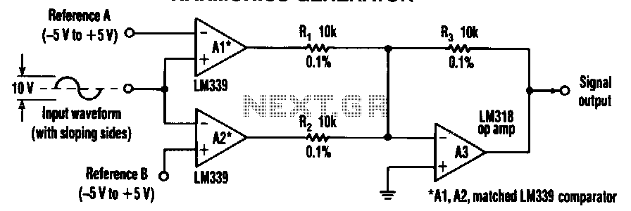
A simple frequency multiplier consists of two comparators and a summing amplifier that generate differential harmonic spectra. This circuit is capable of extracting harmonics from various waveforms, including sine, triangle, sawtooth, or other sloped waveforms. When a sloped-input waveform is applied, a comparator produces an output pulse width that is proportional to the input amplitude plus a reference voltage. By adjusting the reference voltage, the pulse width can vary from 0 to 100%. As the pulse width changes, the harmonic spectrum also varies; however, the combination of two comparators in the adder eliminates specific harmonics based on the duty cycle.
For instance, a pulse with a 50% duty cycle will lack all even-numbered harmonics, while a 25% duty-cycle pulse will omit multiples of the fourth harmonic and include the second, sixth, and tenth harmonics. This circuit can generate multiples of the input frequency that may not be present in the original waveform. By adjusting the reference voltages, virtually any harmonic can be produced. The comparators, denoted as A1 and A2, provide differential inputs to the adder A3, which cancels out equal harmonics. It is essential for both A1 and A2 to exhibit identical AC characteristics, while A3 should possess good common-mode rejection and a high slew rate. Resistors R1, R2, and R3 must match within 0.1% tolerance. The accuracy of the circuit is significantly influenced by the amplitude stability of the input signal.
The frequency multiplier circuit's design relies on precise component selection and configuration. The two comparators (A1 and A2) serve as the primary signal processing elements, converting the analog waveform into a series of pulses. Each comparator's output is influenced by the reference voltage, which can be adjusted to manipulate the pulse width. The summing amplifier (A3) takes the differential outputs from the comparators, allowing for the cancellation of specific harmonics based on their duty cycle. This process enables the circuit to produce a tailored harmonic spectrum.
The performance of the frequency multiplier is contingent upon the matching of resistors R1, R2, and R3, which should be selected for minimal variance to maintain circuit integrity. The common-mode rejection ratio of the summing amplifier is crucial for ensuring that unwanted noise and variations in the input signal do not affect the output. Additionally, a high slew rate in A3 allows for rapid changes in the output, ensuring that the generated harmonics accurately reflect the input waveform's characteristics.
In applications where harmonic generation is necessary, such as in signal processing or waveform synthesis, this frequency multiplier circuit offers versatility and precision. By utilizing adjustable reference voltages and carefully selected components, it is possible to create a wide range of harmonic outputs tailored to specific requirements.Two comparators and a summing amplifier that generate differential harmonic spectra comprise a simple frequency multiplier. The resulting circuit can extract harmonics from a sine, triangle, sawtooth, or any other sloping-sided waveform.
With a sloped-input waveform, a comparator produces an output pulse width that"s proportional to the input amplitude plus a reference voltage. Changing the reference can vary the pulse width from 0 to lOO%. As the pulse width changes, the harmonic spectrum changes, but two comparators combined in the adder eliminate harmonics, depending on the duty cycle.
For example, a 50% pulse will lack all the even-numbered harmonics. Similarly, a 25% duty-cycle pulse will be missing multiples of the fourth harmonic and deliver the second, sixth, and tenth harmonics. Accordingly, the circuit generates multiples of the input frequency that might not have existed in the input waveform.
Adjusting the references can create virtually any harmonic. Because comparators Al and A2 supply differential inputs to the added A3, the adder cancels out equal harmonics. Therefore, both Al and A2 should have identical ac characteristics, and A3 should have good common-mode rejection and a high slew rate.
In particular, Rl, R2, and R3 should match within 0.1%. Of course, the accuracy of the circuit depends heavily on the amplitude stability of the input. 🔗 External reference