
Having 50 input output impedance wideband video amplifier OPA676 circuit

The broadband video amplifier circuit is designed to operate effectively within a frequency range suitable for video signals, typically from 5 MHz to several GHz. The 50-ohm impedance is a standard in RF and video applications, ensuring compatibility with various transmission lines and components.
The amplifier circuit consists of several key components. At the input stage, a matching network may be employed to ensure that the signal from the source is effectively coupled to the amplifier without significant loss or reflection. This network can include resistors, capacitors, and inductors configured to provide the necessary impedance transformation.
Following the input stage, the active amplification element, often a transistor or operational amplifier, is utilized to boost the signal level. The choice of the active device directly impacts the amplifier's bandwidth, gain, and linearity. Proper biasing of the active device is crucial to maintain stability and performance across the desired frequency range.
The output stage of the amplifier also requires careful design to ensure that the output impedance remains at 50 ohms. This can be achieved through additional matching networks or by selecting components that inherently provide the necessary impedance characteristics.
Overall, the design of a broadband video amplifier with a 50-ohm input/output impedance involves careful consideration of component selection, circuit topology, and matching techniques to achieve high performance in signal transmission while minimizing reflections and losses. As shown in Fig having a 50 input/output impedance of broadband video amplifier. In order to achieve a match signal transmission, reducing the reflected signal, often require i nput and output impedance are 50 wideband video amplifier. An amplifier can achieve the above requirements As shown in FIG.
Related Circuits
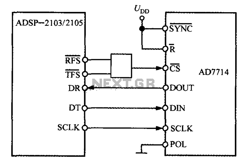
The ADSP-2103 and ADSP-2105 are digital signal processors that interface with the AD7714. When the output is active, the ADSP-2103/2105 configuration includes the RFS non-TES non-terminal set to a low level, while the SCLK terminal is configured for serial...
The circuit topology is similar to the previously mentioned amplifier, utilizing the robust IRFP240 and IRFP9240 MOSFET devices as the output pair, along with high-voltage Motorola transistors in the preceding stages. The supply rail voltage is conservatively set at...

A field strength meter utilizing a biased Schottky detector employs a temperature-compensated Schottky diode within an amplified, untuned field strength indicator powered by two AA cells. This device indicates the relative field strength of RF fields ranging from a...
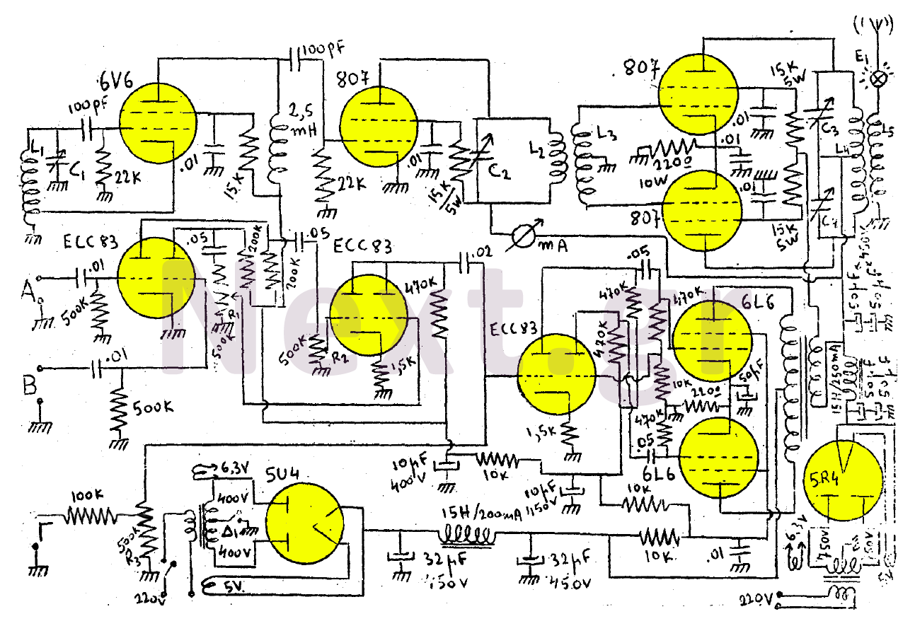
This transmitter consists of a 6V6 oscillator that excites an 807 buffer. The final stage includes two 807 tubes arranged in a Push-Pull configuration. The amplifier is built with three series-connected double-triodes (ECC83) and concludes with two 6L6 tubes...
This is a simple stereo electret microphone preamplifier circuit. For optimal performance, it is recommended to use solid or film capacitors and metal film resistors. The circuit is based on a single IC, the LM358. It is straightforward, cost-effective,...
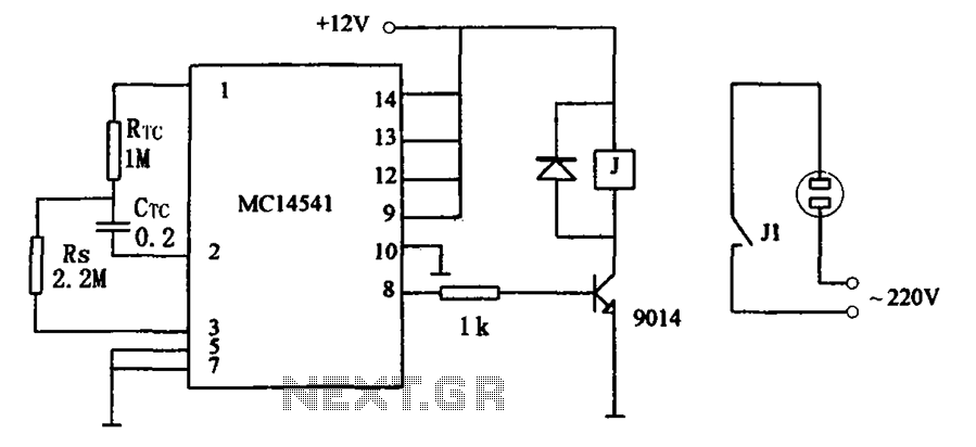
The circuit illustrated in FIG MC14541 is a straightforward timing circuit utilizing the MC14541 integrated circuit (IC). By adjusting the parameter map, the timing can be set for a duration of 3 hours, with options to select various RTC,...