
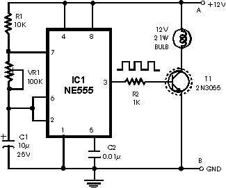
Headlight Flasher
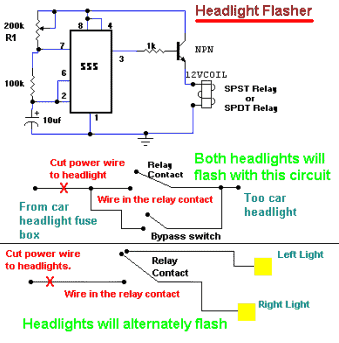
The circuit utilizes a 555 timer IC configured in astable mode, which is ideal for generating a square wave output. This mode allows the circuit to toggle the headlights between on and off states at a frequency determined by the external resistors and capacitors connected to the timer. The timing period can be modified by adjusting resistor R1, which influences the charge and discharge cycles of the timing capacitor, thereby controlling the flash rate of the headlights.
To implement this circuit within a vehicle, the first step involves identifying the positive wire leading from the fuse box to the headlights. This wire must be severed to integrate the circuit. The relay contact is then introduced into the circuit, allowing the 555 timer to control the power supplied to the headlights. The bypass switch is an essential component, as it permits the driver to revert to standard headlight functionality without engaging the flashing feature. This is particularly useful during regular driving conditions when continuous illumination is required.
For the alternating headlight configuration, the installation process requires cutting the positive wire that leads to each headlight separately. This modification allows the circuit to alternate the activation of each headlight, creating a distinctive flashing effect that can enhance visibility and attention in various driving situations. Proper connection and insulation of all wires and components are crucial to ensure safety and reliability in operation. Additionally, it is recommended to use a relay rated for the current and voltage specifications of the vehicle's headlight system to prevent overheating and potential failure.It will allow your car headlights to flash on and off at the same time or it will cause them to flash alternately. The circuit is based on the 555 timer. It is used in the astable mode. The 555 timer output will go high for an adjustable period of time and then turn off. It will then repeat the procedure. The time is adjusted by R1. To hook up the circuit to your car you must locate the positive wire from the fuse box to the headlights. Cut the wire and insert the relay contact and bypass switch. The bypass switch will allow you to bypass the relay contact for normal headlight operation. In the alternateing headlight configuration you must cut the positive wire to each headlight and wire in the relay contact.
🔗 External reference
Related Circuits
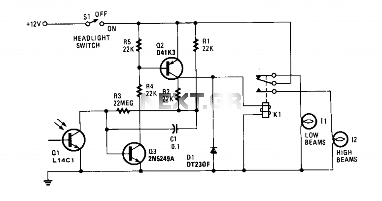
When the lights of an oncoming car are detected by the photo-transistor Q1, the circuit activates. Sensitivity is adjusted by the 22-megohm resistor, R5, to approximately half a foot-candle. The relay employed has a 12-volt, 0.3A coil. The L14C1...
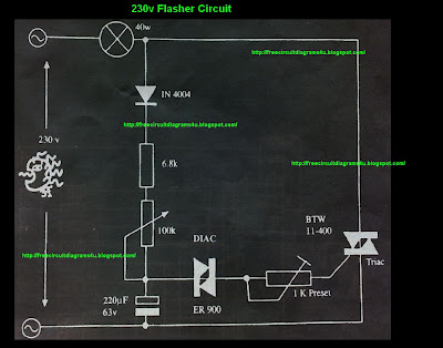
This circuit operates with 230V and can be used to decorate parties. It features a DIAC ER 900 and a TRIAC BTW 11-400. The circuit utilizes a DIAC (Diode for Alternating Current) and a TRIAC (Triode for Alternating Current) to...
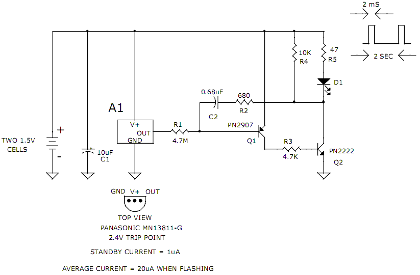
The hobby circuit described can be connected to a 3V battery to provide a warning when the battery is nearing its end of life. It will flash an LED when the battery voltage drops to approximately 2.4 volts. The...
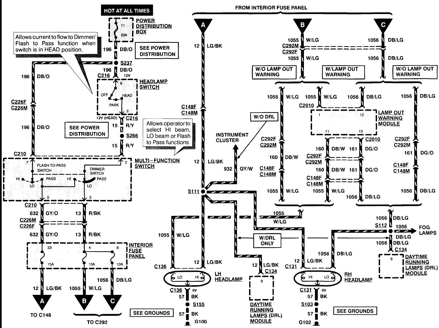
A 1996 Ford Explorer has non-functional headlights. The vehicle has operational low beams and interior lights. The owner has replaced the bulbs, checked the fuses, relays, and light switch, yet the headlights remain inoperative. Suggestions are requested to identify...
This circuit is a modified flasher designed to control the on and off operation of a bulb instead of an LED. It employs a 555 timer integrated circuit (IC) configured as an astable multivibrator. The flashing frequency can be...

Individuals seeking a distinctive gift for Christmas and New Year may find this project appealing. Certification of this project will undoubtedly create a preference for it. The project in question appears to be a creative endeavor aimed at providing a...