
Hi-Fi DX Bass circuit

The passive DX bass circuit operates by manipulating audio signals to enhance the bass response while maintaining a balanced output across the frequency spectrum. The circuit consists of two main stages: the tone control stage and the compression stage.
In the tone control stage, the 0.01 µF capacitor is strategically placed to filter out high-frequency signals, allowing the lower frequencies to be amplified and balanced with the treble. The 0.22 µF capacitor serves a similar purpose for low frequencies, ensuring that the bass response is pronounced without overwhelming the overall sound quality. This stage is crucial for achieving a desirable sound profile, especially when paired with various audio amplifiers.
The second stage focuses on sound compression, which is essential for managing audio dynamics. The capacitors in this stage are tasked with initiating the compression process, which helps to prevent distortion and maintain clarity at higher volumes. The introduction of the 2.2 kΩ resistor plays a significant role in delaying the sound, effectively multiplying the compression effect. This delay can enhance the perceived richness of the bass, making it more impactful during playback.
The 10 kΩ variable resistor provides flexibility in tuning the circuit to suit different speaker configurations. Adjusting this resistor allows users to optimize the circuit's performance based on the specific frequency response of their speakers. For smaller hi-fi speakers, setting the resistor to 0 ohms minimizes the compression effect, allowing for a more natural sound reproduction.
Overall, the passive DX bass circuit is versatile and user-friendly, making it suitable for a wide range of audio applications. Its design encourages experimentation and adaptation, empowering users to modify the circuit to meet their individual preferences while ensuring high-quality audio output.Here is the circuit diagram of a passive DX bass circuit that can be used with almost all audio amplifiers. This circuit is designed by Mr. Emmanuel Chipula ( emmanuel@windowshoppingmalawi. com ) from Malawi and was sent to us for publication. We tested this circuit in our lab and the result was fine. Full credit of this circuit goes to Mr. Emmanuel C hipula and we thank him for his contribution. Emmanuel`s comments on the circuit : The circuit that I have designed is a passive one but you can make it an active one by adding a pre amp at the output. The first stage acts as a main tone stage. It balances the bass and the treble. The 0. 01 cap is for high frequency while the 0. 22uF cap is for low frequency. The second stage is for sound compression. the caps works the same as at the first stage only that they are there to start the sound compression that is received from the input stage.
The 2. 2k resistor delays the sound thereby multiplying the compression. The 10k variable resistor is there used to tune the compression depending on the frequency of the speaker. If you are using 4 to 6 inches hi-fi speakers, I advise you to keep the 10k variable resistor at 0 ohm.
The circuit is not copyrighted and you can change it to suit your requirement. All I ask is to be posting the updates of the circuit design on the site. 🔗 External reference
Related Circuits
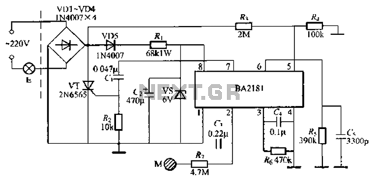
The BA2181 is a dimming controller that utilizes ASIC technology for touch-based stepping dimming of lights. It operates with low power consumption and has strong anti-interference capabilities. The device is compact and stable, making it suitable for various applications....

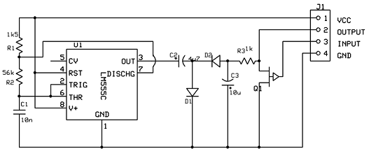
This is an infrared-based broken beam alarm designed to protect doors and entry passages. It emits a loud alarm when someone crosses the invisible infrared barrier. The infrared-based broken beam alarm system operates by utilizing a pair of infrared emitters...
Our programmable MP3 player has an interface to an LCD with a HD44780 controller. These are alphanumeric LCDs with one to 4 lines of text and 16 to 40 characters per line. However, these LCDs (and LCDs in general)...

Application of the differential amplifier circuit in OTL amplifier circuits. The differential amplifier circuit is a fundamental building block in various electronic applications, particularly in output transformerless (OTL) amplifier circuits. An OTL amplifier is designed to drive loads directly...
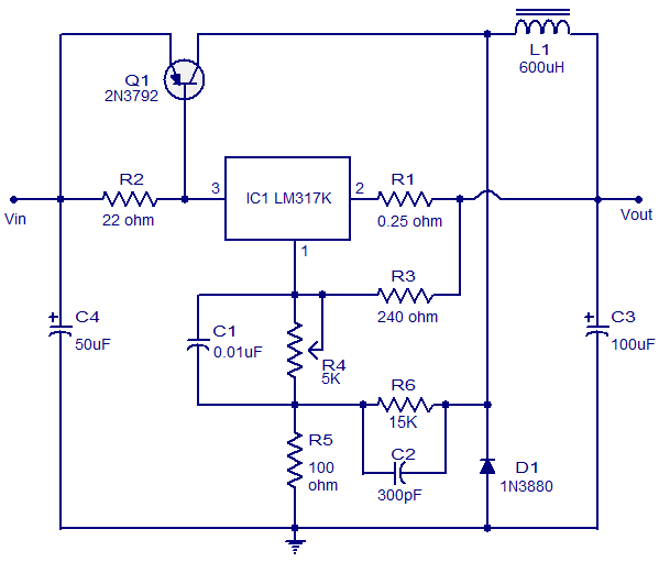
This circuit illustrates a 3A Switching Regulator Circuit based on the LM317K integrated circuit. It is designed to be simple and cost-effective. The 3A Switching Regulator Circuit utilizing the LM317K IC serves as a versatile voltage regulation solution, capable of...
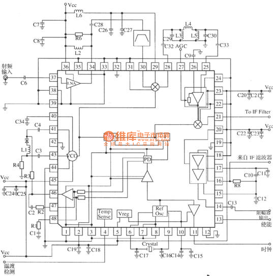
MRFICl505R2 is a 1.575GHz GPS downconverter chip. It integrates a mixer, VCO, PLL, crystal oscillator, A/D converter, loop filter, and other circuits. The MRFICl505R2 IF output frequency is 4.1MHz, with a typical conversion gain of 105dB, an operating voltage...