
Hi-Fi Preamplifier

Additional Content: The circuit design by Graham Maynard showcases an impressive high frequency response. This characteristic is evident when a 100kHz squarewave is applied to the input, a common test for assessing the high-frequency performance of a circuit. This feature makes it suitable for applications that require accurate and fast response to high-frequency signals.
The circuit's performance was further verified using Tina Pro, a powerful circuit simulation software. This tool was used to generate response graphs, which provide a visual representation of the circuit's behavior under different conditions. These graphs are crucial in analyzing the circuit's performance, as they can reveal potential issues such as distortion, noise, and instability that might not be apparent from a simple inspection of the circuit diagram.
In conclusion, the circuit submitted by Graham Maynard is a high-performance design that excels in handling high-frequency signals. Its performance has been thoroughly tested and verified, making it a reliable choice for high-frequency applications.This circuit was submitted by Graham Maynard from Newtownabbey, Northern Ireland. It has an exceptionally good high frequency response, as demonstrated by applying an 100kHz squarewave to the input. I have produced some response graphs using Tina Pro to highlight these characteristics. 🔗 External reference
Related Circuits
High-quality, discrete component design for input and tone control modules to complement the 60-watt MOSFET audio amplifier with a high-quality preamplifier design. The circuit design focuses on creating a high-fidelity audio preamplifier that enhances the performance of a 60-watt MOSFET...
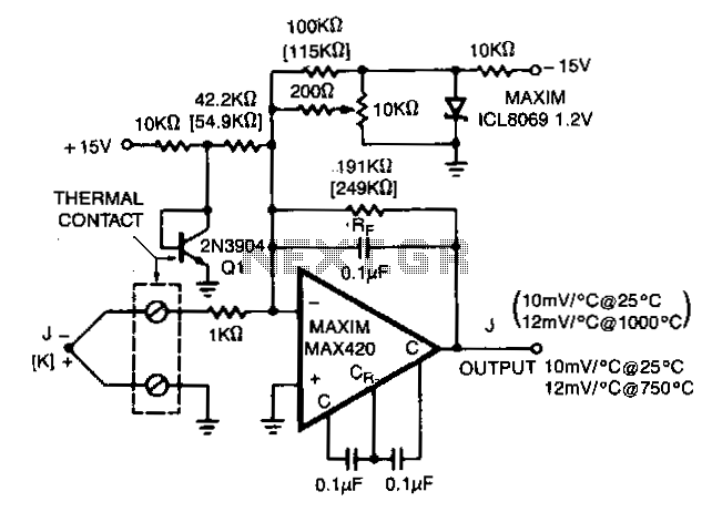
The MAX420 is operated at a gain of 191 to convert the 52 µV/°C output of the type J thermocouple to a 10 mV/°C signal. The -2.2 mV/°C temperature coefficient of the 2N3904 is added into the summing junction...
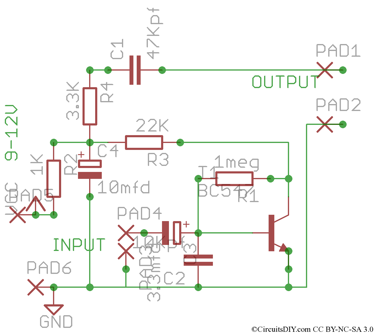
This circuit consists of a single transistor functioning as an amplifier, providing significant amplification for weak and unipolar signals, which can then be fed into a more powerful amplifier. The described circuit utilizes a single transistor in a common-emitter...
This project is one for the experimenter, but as shown will work extremely well. The sensing circuit can be made so sensitive that a load of only 2.5mA is enough for the circuit to detect, and disconnect the charger....
In an audio amplifier, the quality of sound depends on several factors, including the quality of active and passive components, circuit configuration, and layout. The selection of components is influenced by the constructor's budget. Discrete active components like transistors...
Nowadays, audio signal preamplifiers are utilized in numerous electronic devices. There are various types of audio preamp circuits, ranging from simple to complex designs. This document presents an effective design of a compact signal preamplifier circuit, which is ideal...