
Hi-lo temperature sensor

The described circuit utilizes a bridge configuration comprising resistors R1, R2, and two additional 2.2 kΩ resistors. In this setup, R2 functions as a thermistor, which is a temperature-dependent resistor. The resistance of R2 varies with temperature, allowing it to serve as a sensing element in the circuit. R1 is configured to establish a reference temperature threshold, which dictates when indicator LED L2 will illuminate.
The bridge circuit operates on the principle of balancing the resistances. When the temperature sensed by the thermistor R2 deviates from the set point defined by R1, the balance of the bridge is disturbed. This imbalance results in a voltage change at the output of the bridge circuit, triggering the appropriate response from the indicator LEDs. Specifically, if the temperature exceeds the designated threshold, LED L1 will light up, signaling an over-temperature condition. Conversely, if the temperature falls below the threshold, LED L3 will illuminate, indicating an under-temperature condition.
The use of a thermistor in this application is critical due to its sensitivity to temperature changes, allowing for precise monitoring and indication of temperature variations. The two 2.2 kΩ resistors are likely employed to complete the bridge and ensure that the circuit remains stable across a range of operating conditions. The overall design is effective for applications requiring temperature monitoring and alerting, providing visual cues for temperature management.Resistors Rl, R2, and the two 2.2 k resistors form a bridge circuit. R2 is a thermistor, and Rl sets the temperature at which L2 lights. Lower or higher temperatures light LI or L3 to indicate an over- or under-temperature condition.
Related Circuits

Close to human perception and stable color sensing is a pervasive challenge encountered in various disciplines, such as machine vision for classification and recognition, as well as in intelligent systems like smart illumination systems in home or workplace environments....

The circuit utilizes the principle that the forward voltage of a silicon diode changes in a relatively linear manner with temperature when supplied by a constant current source. Diode D1 and resistor R2 create a potential divider connected to...

The UV TRON flame sensor, manufactured by Hamamatsu Photonics in Japan, is an ultraviolet light detector with a spectral sensitivity range of 185 nm to 260 nm. It is completely insensitive to visible and infrared light, eliminating the need...

In this circuit, an LM34 or LM35 generates a frequency that is proportional to temperature. The reference current (138) is established through resistor R3. The output can be utilized to drive a display, frequency counter, or other indicating devices...
A few years ago, a diode-sensor based RF power meter was built using a 68HC11 microprocessor. Prior to that, an analog RF power meter with a thermal power sensor was developed. The datasheets for logarithmic amplifiers, which promised a...
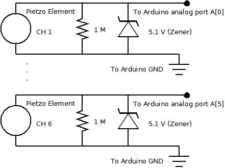
The piezo element is connected solely to Channel 1 (Arduino A[0] port). Channels 1 through 6 are linked to female mono jacks, with the ground (GND) wiring arranged in series from jacks 1, 2, and 3, continuing to the...