
Hi-Low Logic Digital tester

The circuit operates by utilizing a 7-segment LED display configured as a common cathode, which allows each segment to be illuminated by applying a high signal to the appropriate segment pin. The logic level tester interprets digital input signals and displays corresponding values on the 7-segment display. When the input signal is high (logic level '1'), the display shows an 'H'. Conversely, when the input signal is low (logic level '0'), the display shows an 'L'. In cases where the input is not connected, the display indicates 'N' for open.
The core of the circuit relies on a TTL NAND gate integrated circuit (74LS00), which contains four 2-input NAND gates. These gates are used to process the input signal and determine which segments of the display should be activated. The transistors in the circuit serve as switches, allowing the control signals from the NAND gates to drive the segments of the display without exceeding the current ratings of the logic gates.
Resistors R1, R2, R5, and R6, each with a value of 10 kOhm, are used for biasing and current limiting, ensuring that the transistors operate within safe limits. Resistor R3, valued at 47 kOhm, may be used for pull-down purposes or to set the base current for one of the transistors. Resistor R4, at 8.2 kOhm, is likely utilized to limit the current to one of the segments of the display. Resistors R7, at 4.7 kOhm, and R8-R12, each at 330 Ohm, are employed to control the current through the segments of the display, ensuring they illuminate correctly without damage.
In summary, this circuit effectively demonstrates the logic levels of digital signals using a 7-segment display, powered by a TTL NAND IC and controlled by transistors, with carefully selected resistor values to manage current and voltage levels throughout the system.This tester, the logic level digital signals indicate on a 7-segment display. The display shows an H as the input signal is high. When the signal is low, the display shows an L on. If the input is open, the display shows N. The circuit consists of a TTL NAND IC type 74LS00 and three transistors. The NAND gates ensure that the right segments of the display can be controlled. The display is of the type CC (common cathode ie common cathode). R1, R2 = 10 kOhm R3 = 47 kOhm R4 = 8.2 kOhm R5, R6 = 10 kOhm R7 = 4.7 kOhm R8-R12 = 330 ? LD1 = 7 segment LED display (common cathode) IC1 = IC TTL 74LS00 🔗 External reference
Related Circuits
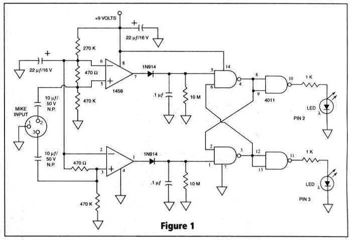
Many things can go wrong in a modern recording studio, but few are as difficult to track down as reversed microphone polarity. When a microphone is placed in front of a sound source, a positive pressure on its diaphragm...
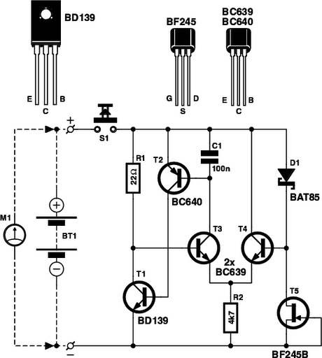
Determining whether a battery is empty or if there is a fault with a device can be challenging when a battery-powered device, such as a Walkman, fails to power on. Before seeking professional repair, it is advisable to test...
Use this circuit to test if the light coming from your 40kHz IR emitter is really emitting the right frequency. The schematic says to use a GP1U5X IR module, but probably any 40kHz detector module will work. I used...
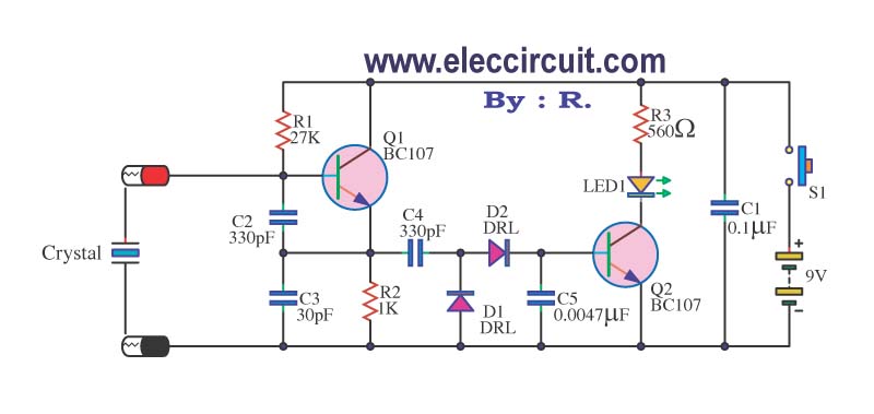
A multimeter cannot be used to test a crystal oscillator. Instead, a dedicated circuit is required, capable of checking crystals within the frequency range of 100 kHz to 900 MHz. This circuit is easy to construct and cost-effective. To construct...
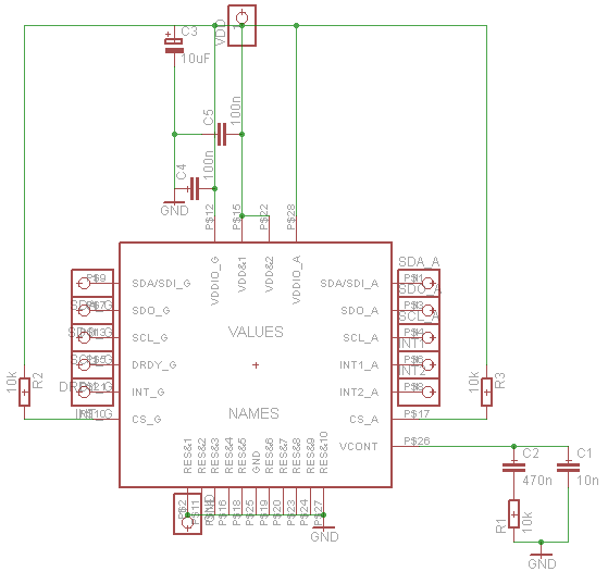
Establish communication between the microcontroller unit (MCU) and the accelerometer using either I2C or SPI protocols. It has been noted that shorting the phase-locked loop (PLL) filter input in the device does not affect the readings from the gyroscope...
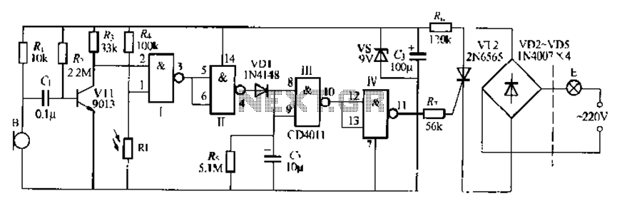
The CDI011 integrated circuit is designed for a sound and light-controlled stair delay switch circuit, which is relatively simple and effective. It utilizes a combination of NAND gates and differential input dynamics. The circuit has two input terminals; when...