
High Gain JFET Audio Amplifier

The JFET (Junction Field Effect Transistor) audio amplifier circuit is designed to amplify audio signals while maintaining low power consumption. The circuit typically consists of a JFET transistor configured in common source mode, which is known for its high voltage gain characteristics. The input signal is applied to the gate terminal of the JFET, and the output is taken from the drain terminal.
In this configuration, the JFET operates by controlling the flow of current between the source and drain terminals based on the voltage applied to the gate. The gate is reverse-biased, which allows for high input impedance and minimal loading on the preceding stage of the audio signal source. This feature is particularly advantageous in audio applications, as it preserves the integrity of the original signal.
The circuit also includes biasing resistors connected to the gate and drain to establish the proper operating point for the JFET, ensuring that it remains in the active region during operation. Capacitors may be used for coupling the input and output signals, blocking any DC components while allowing AC signals to pass through.
Furthermore, the design can be enhanced by incorporating feedback mechanisms to stabilize the gain and improve linearity. By adjusting the values of the resistors and capacitors, the gain can be tailored to meet specific application requirements.
Overall, this simple high-gain JFET audio amplifier circuit is suitable for various audio applications, including microphones, musical instruments, and other low-level audio sources, providing an efficient solution for signal amplification.This is a simple high gain JFET audio amplifier circuit. This circuit need very low power but it provides high gain amplifying function. It also called `JFET.. 🔗 External reference
Related Circuits
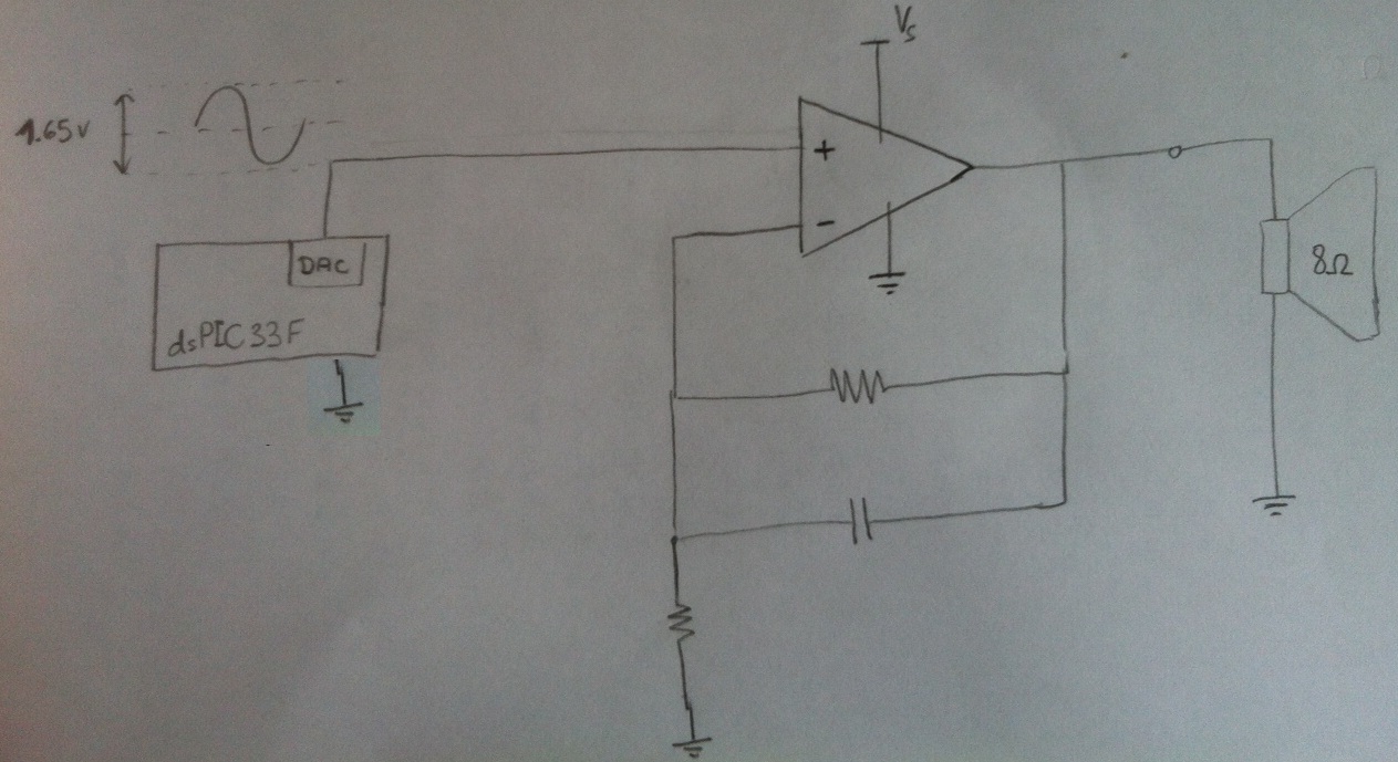
Design a circuit in which a microcontroller produces a signal and then uses an amplifier to drive an 8-ohm speaker. The LM386 has been used previously, but it cannot exceed 1W, which is insufficient. Additionally, a second-order anti-aliasing low-pass...
The TMB-1 is an RF amplifier unit and receiving accessory compatible with low-impedance broadband loops, high-impedance terminated loops (such as Pennant, Flag, or Kaz Delta), and whip (telescoping rod) antennas. This design is optimized for operation within the frequency...
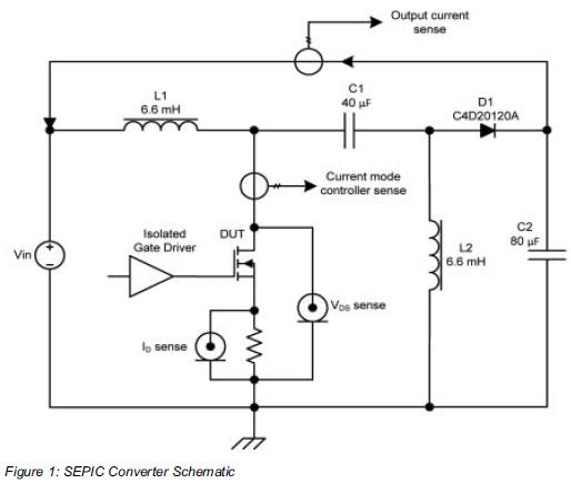
Comparing the performance of 1200V silicon carbide (SiC) MOSFETs with 1200V silicon MOSFETs and IGBTs at high frequency is essential to identify the differences in device losses and power-handling capabilities among these technologies. A demonstration platform has been developed...
The SL517 is designed as an audio, RF, or infrared decoder circuit suitable for electronic toy applications. The internal circuitry consists of an analog amplifier, a frequency divider, a bistable circuit, and a driver. It utilizes CMOS technology, has...

Circuit with electronic symmetrical input, with possibility of regulation of the gain from the pontesometer RV1 and the level of signal with the RV2. The quality of pontesometer RV1 (as other material), should be very good, in order to...
Construct a basic audio amplifier utilizing transistors. While integrated circuit (IC) designs are available for this purpose, the intention is to use transistors to gain practical knowledge about their amplification capabilities. The article "Amplifier Basics - How Amps Work...