
High Impedance Voltmeter LM358

This circuit utilizes a high-impedance buffer configuration to mitigate the loading effect of the voltmeter on high-resistance circuits. The primary component of this design is an operational amplifier (op-amp) configured as a voltage follower. The op-amp has a very high input impedance, typically in the range of megaohms, which allows it to measure voltage without significantly affecting the circuit being tested.
In this configuration, the input of the op-amp is connected to the point in the circuit where voltage measurement is desired. The output of the op-amp is then connected to the multimeter for voltage reading. This design ensures that the input impedance of the measuring device does not load the circuit under test, allowing for accurate voltage readings even in high-resistance scenarios.
The power supply for the op-amp can be derived from a dual power supply or a single supply with appropriate biasing to ensure that the output voltage remains within the operating range of the multimeter. Additionally, decoupling capacitors should be placed close to the power supply pins of the op-amp to minimize noise and improve stability.
To further enhance the performance of the circuit, a resistor can be placed in series with the output of the op-amp to limit current and protect the multimeter from potential over-voltage conditions. It is also advisable to include a protection diode at the input stage to prevent any negative voltages from damaging the op-amp.
This high-impedance voltmeter circuit is particularly useful in applications such as testing sensor outputs, measuring voltages in high-impedance environments, and when working with delicate electronic components that may be sensitive to loading effects. Overall, this design provides a cost-effective solution for accurate voltage measurements in high-resistance circuits.This circuit is designed to provide an inexpensive way to to create a High Impedance Voltmeter while making use of an inexpensive analog or digital multimeter. When measuring voltages in high resistance circuits the resistance of the voltmeter itself has an effect on the circuit.
For example if the voltage across a 1 megohm resistor is measured with a voltmeter that has an internal resistance of 1 megohm then the total resistance in that part of the circuit is effectively halved (two 1 M resistors in parallel = 500K ohms). In another example; If a voltmeter with a 1 megohm resistance is placed in series with a 1 megohm resistance there will in effect be two - 1 megohm resistances in series, the resistor in the circuit and the resistance of the voltmeter. Under these conditi 🔗 External reference
Related Circuits
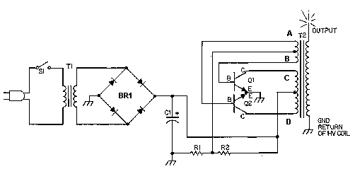
This circuit is designed to demonstrate high frequency and high voltage, capable of producing up to approximately 30 kV, depending on the transformer utilized. It is an economical and straightforward project, primarily using a standard TV flyback transformer. The...
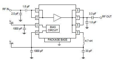
The RF2126 high-power linear amplifier IC, manufactured by RFMD, can be utilized to design a simple yet highly efficient amplifier for 2.45 GHz ISM applications, including WLAN and POS terminals. This component also serves as the final stage in...
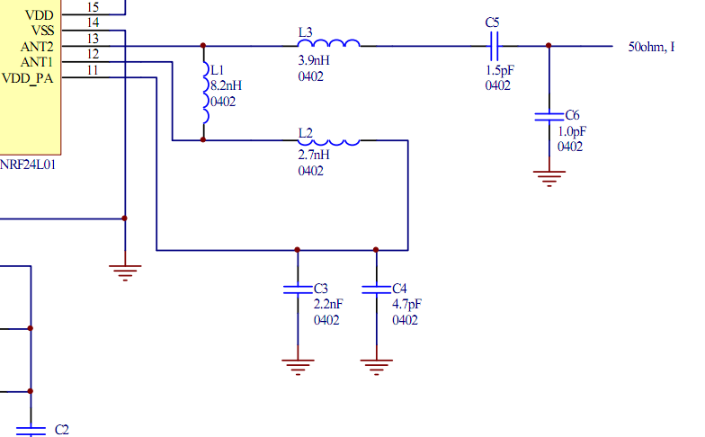
Place the transceiver and the chip antenna very close together, eliminating the need for a 50-ohm transmission line. If this is the case, can the two matching circuits be merged into one to reduce the component count? To create an...
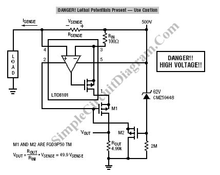
The LTC6101 operational amplifier can be utilized for high-voltage current monitoring and sensing. This circuit is capable of sensing current in a 500-volt system. Here is the schematic diagram. The LTC6101 is a high-voltage current sense amplifier designed specifically for...
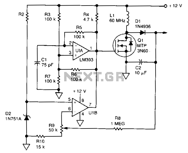
U1 is a dual voltage comparator with open collector outputs. The A side functions as an oscillator operating at 100 kHz, while the B side is part of the regulation circuit that compares a fraction of the output voltage...
A composite amplifier can be constructed that offers high gain, wide bandwidth, and good DC accuracy by cascading the sections of a dual video amplifier and incorporating two suitable phase compensation components. The operational amplifier drives a 150-ohm load...