
High Pass Filter Tutorial

The passive high pass filter circuit is an essential component in electronics, designed to allow signals with a frequency higher than a certain cutoff frequency to pass through while attenuating signals with frequencies lower than the cutoff. This type of filter typically utilizes resistors (R) and capacitors (C) in its construction, forming an RC circuit that defines its frequency response characteristics.
The first-order passive high pass filter consists of a resistor and a capacitor arranged in series, with the output taken across the resistor. The cutoff frequency (fc) is determined by the values of the resistor and capacitor using the formula:
fc = 1 / (2πRC)
In this equation, fc is expressed in hertz (Hz), R in ohms (Ω), and C in farads (F). At frequencies above the cutoff, the output voltage across the resistor increases, while at frequencies below the cutoff, the output voltage decreases significantly.
The Bode plot is a graphical representation of the filter's frequency response, illustrating how the gain and phase shift of the output signal vary with frequency. The gain plot typically shows a slope of +20 dB/decade above the cutoff frequency, while the phase plot indicates a phase shift that approaches +90 degrees as frequency increases.
Construction of a passive high pass filter is straightforward. The components required include a resistor, a capacitor, and a breadboard or PCB for assembly. The resistor and capacitor are connected in series, and the output is taken from the junction between the resistor and the capacitor. Proper consideration should be given to the power ratings and tolerances of the components to ensure reliable performance within the desired frequency range.
In summary, the passive high pass filter is a fundamental circuit utilized in various applications, including audio processing, signal conditioning, and communication systems, where it is necessary to eliminate unwanted low-frequency noise while preserving higher frequency signals.Electronics Tutorial about Passive High Pass Filter Circuit including Passive RC High Pass Filter First Order Frequency Response, Bode Plot and Construction.. 🔗 External reference
Related Circuits

Long-distance high-voltage direct current (HVDC) lines transmit hydroelectricity from Canada's Nelson River to a converter station, where it is converted to alternating current (AC) for use in southern Manitoba's electrical grid. HVDC systems utilize direct current for bulk power...

A circuit is needed to drive three or more LEDs at a current of 200-350mA each, with the capability to randomly flash or strobe them at a frequency of 5-20Hz. The input power should be low-voltage DC, with a...
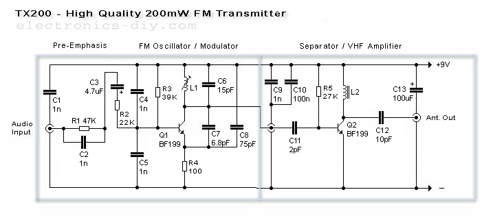
The TX200 is an advanced and significantly larger VFO/VCO FM transmitter, recognized as one of the best transmitters available. It is a 200mW FM transmitter designed for stereo PLL applications, providing a wide range for broadcasting music throughout a...
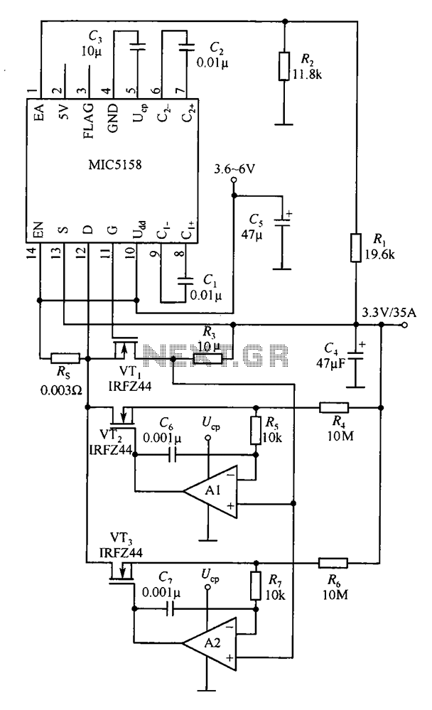
The MIC5158 is designed to manage tasks by controlling multiple external N-channel MOSFETs in parallel, which enables high current or high power output for a linear regulator circuit. This is illustrated in the accompanying figure. The operational amplifier circuit...
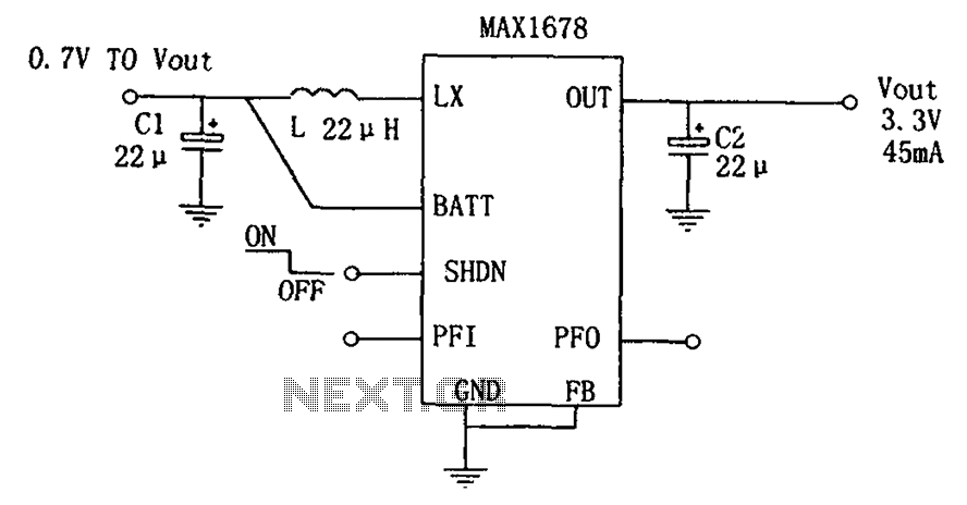
As depicted in the figure, this circuit is suitable for high-efficiency single-cell battery power boosting. It comprises a MAX1678 integrated circuit and three external components. The MAX1678 is designed for low-power applications and features an ultra-small 8-pin MAX package....
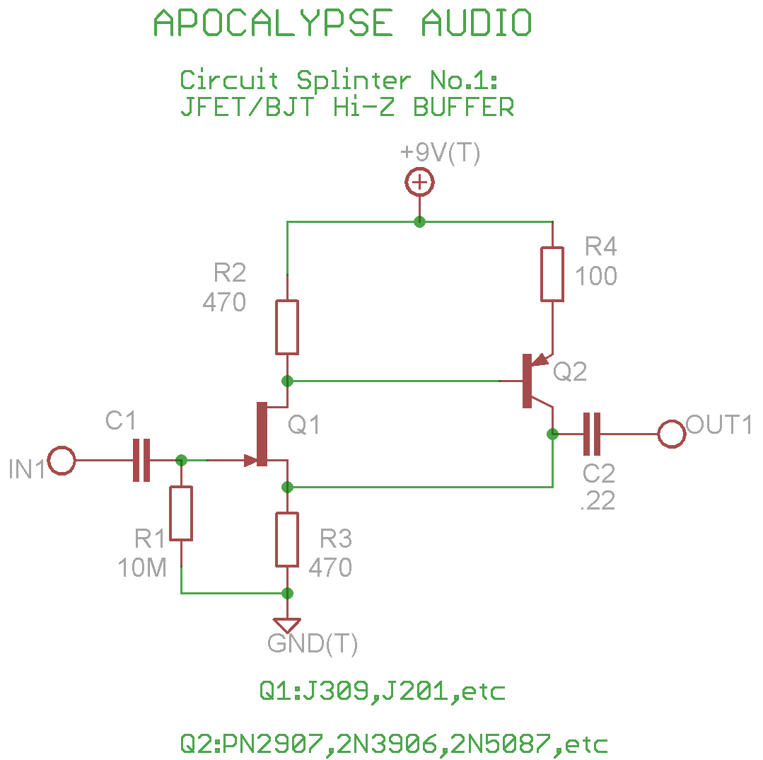
This is a common circuit often found in various resources, yet it appears to be less prevalent in stompbox applications. The circuit utilizes an NPN JFET DC coupled with a PNP BJT. The FET provides a significantly higher input...