
High-power battery-operated flasher

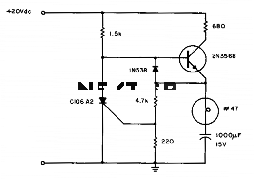
The flip-flop timing is regulated by a conventional UJT (Unijunction Transistor) oscillator configuration, which includes components such as Q1, R1, and C3. Potentiometer R2 and diode CR1 ensure independence in on/off timing. A photoconductor, designated as PC1, disables the UJT firing circuit during daylight hours.
This flasher circuit is designed for efficient operation in automotive and marine environments, utilizing a 12-volt power supply. The output power range of 36 to 40 watts is suitable for various lighting applications, ensuring visibility in low-light conditions. The variable flash rate feature allows customization based on user preference or regulatory requirements, with a maximum frequency of 60 flashes per minute.
The core of the flasher's functionality lies in its flip-flop mechanism, constructed using silicon-controlled rectifiers (SCRs). SCR1 and SCR2 alternate the current flow to the load, creating the flashing effect. The design allows for one SCR to control the lamp load while the other remains grounded, which is critical in applications where a negative potential is required.
The timing of the flashing is managed by a UJT oscillator, which provides a stable pulse output. The inclusion of resistors (R1) and capacitors (C3) determines the frequency and duration of the flashes. Potentiometer R2 offers a means to adjust the timing characteristics, allowing for fine-tuning of the on and off cycles to meet specific operational needs. Diode CR1 plays a crucial role in ensuring that the timing of the flashes is independent of the photoconductor's operation.
The photoconductor (PC1) is a vital component that enhances the automatic functionality of the flasher. It senses ambient light levels, effectively locking out the UJT firing circuit during daylight hours to prevent unnecessary activation of the flasher. This feature not only conserves energy but also extends the lifespan of the flasher by reducing wear during daylight conditions.
Overall, this flasher circuit design is a robust solution for applications requiring reliable and efficient flashing signals, combining advanced timing control with automatic day/night operation.This flasher operates from a 12-volt car or boat battery. It offers 36 to 40-watts output, variable flash rate (up to 60 flashes per minute), independent control of both on and off cycles and photoelectric night and day control that turns the flasher on at night and shuts it off during the day for automatic operation. SCR1 and SCR2 form a basic dc flip-flop. The lamp load is the cathode leg of one SCR so that the other side of the load may be at ground (negative) potential (required in some applications).
The flip-flop timing is controlled by a conventional UJT oscillator arrangement (Ql, Rl, C3, etc.). Potentiometer R2 and diode CR1 provide on/off timing independence. Photoconductor PCI locks out the UJT firing circuit during the daylight hours.
Related Circuits
The LED flasher circuits below operate on a single 1.5 volt battery. The circuit on the upper right uses the popular LM3909 LED flasher IC and requires only a timing capacitor and LED. The top left circuit, designed by...
The hobby circuit described can be connected to a 3V battery to provide a warning when the battery is nearing its end of life. It will flash an LED when the battery voltage drops to approximately 2.4 volts. The...
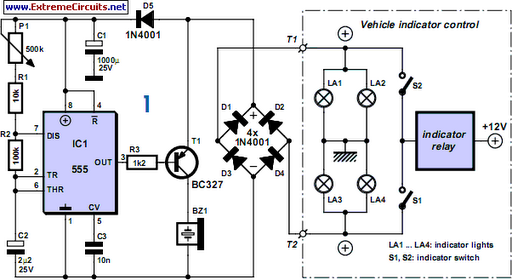
For bikers or scooter riders, it is easy to forget to cancel flashing indicators after turning without an audible reminder. Constantly checking indicator lamps is not practical; attention should remain on the road. The circuit presented here offers an...

The LED flasher circuits below operate on a single 1.5 volt battery. The circuit on the upper right uses the popular LM3909 LED flasher IC and requires only a timing capacitor and LED. The top left circuit, designed by...
Flashing occurs each time the capacitor discharges through the turned-on SCR. When the discharge current falls below the SCR holding current, the SCR turns off, and the capacitor begins charging for another cycle. The circuit will maintain a slower...
The UBA2021 can be utilized as a 600 V lamp controller and half-bridge driver integrated circuit (IC) for high-power applications. It is designed for long-life compact fluorescent lamp (CFL) and tubular fluorescent lamp (TL) applications. The UBA2021 is a versatile...